Moving the KRMx02
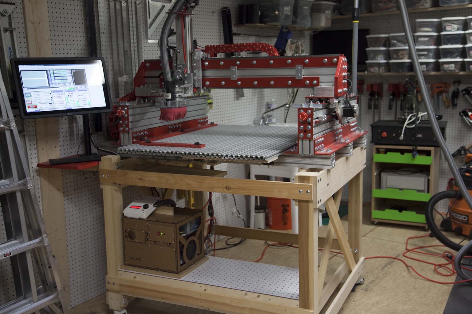
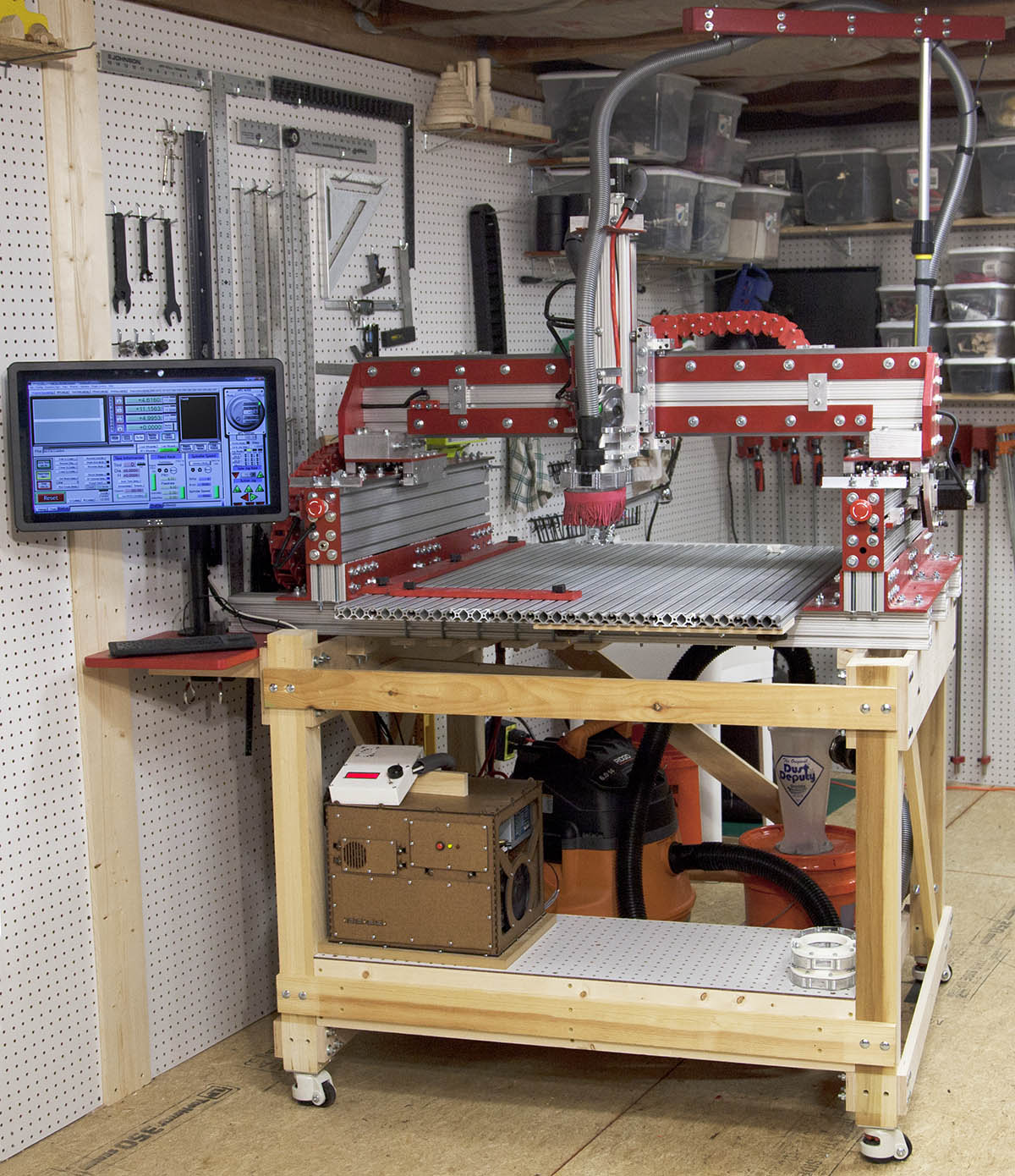
Recently we completed a new larger workshop and lab and had moved all the equipment except the KRMx02 CNC. This machine is a 30x27 build and weighs in at almost 544lbs so it would require a little fineness.
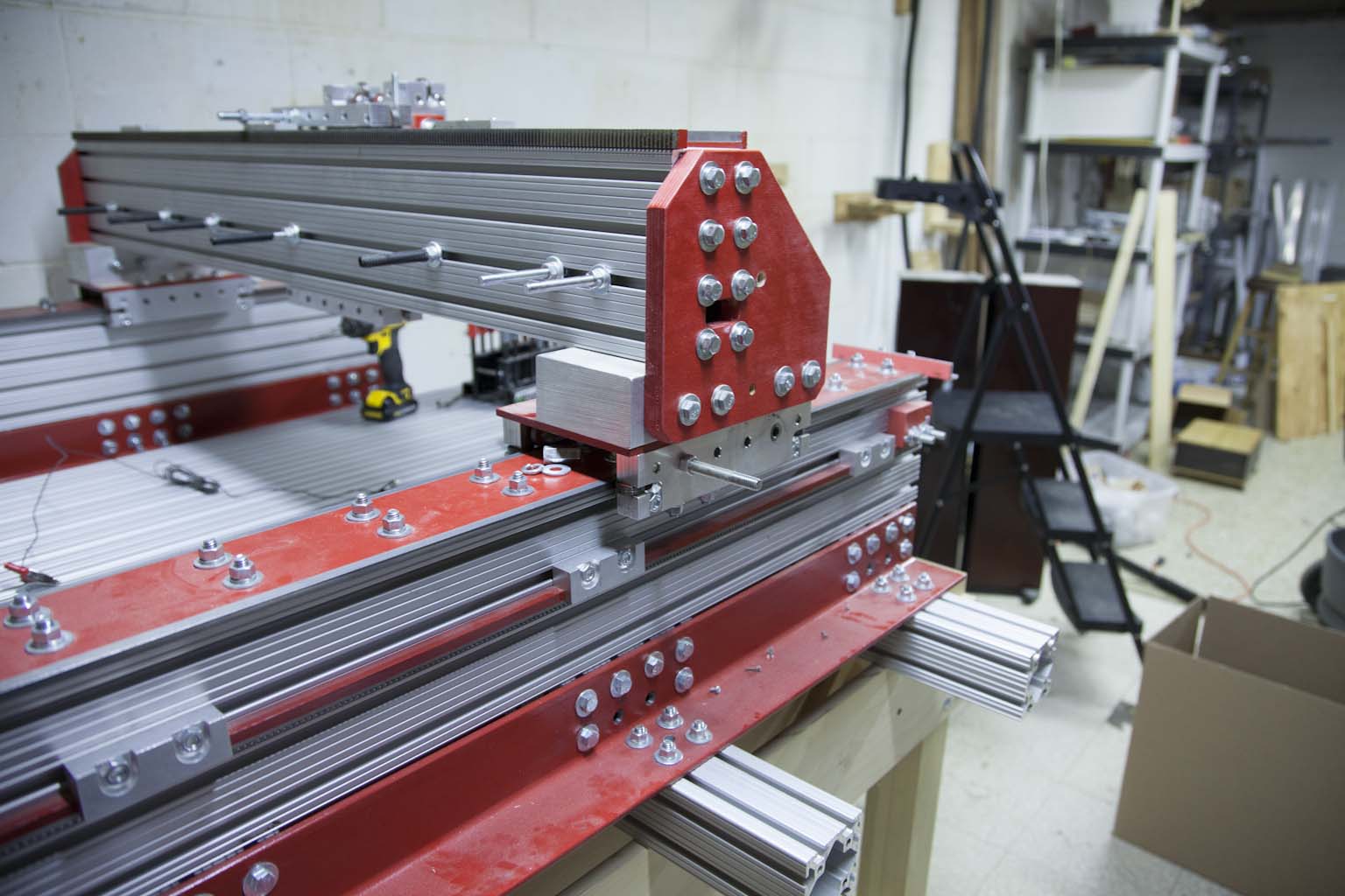
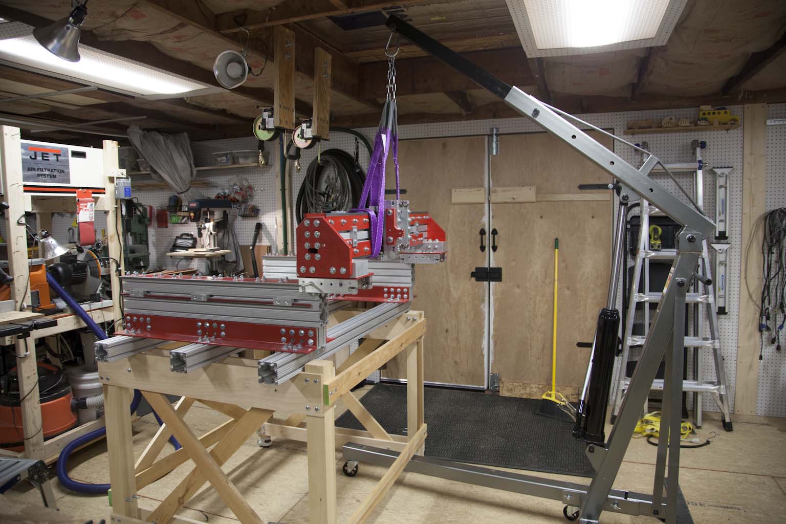
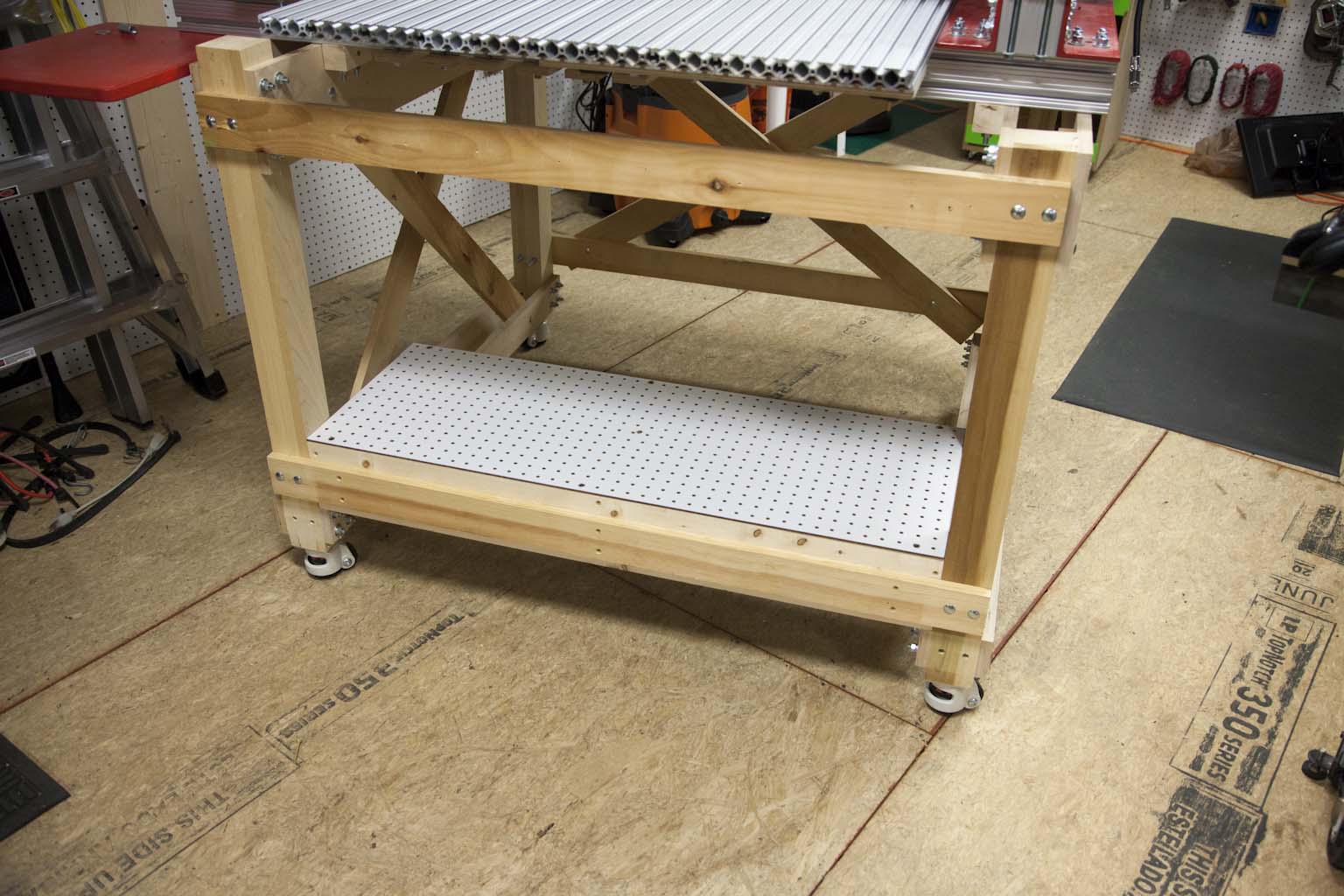
The image below shows the machine in its final resting position, but I wanted to document what I did to facilitate the move with as little disruption as possible.
KRMx02's new home
Let's do this
Keep in mind that your KRMx02 my require a different approach as you may have built a different stand or build size. This machine is moving from a basement workshop with a 34" door opening.
Step 1 - Remove Accessories
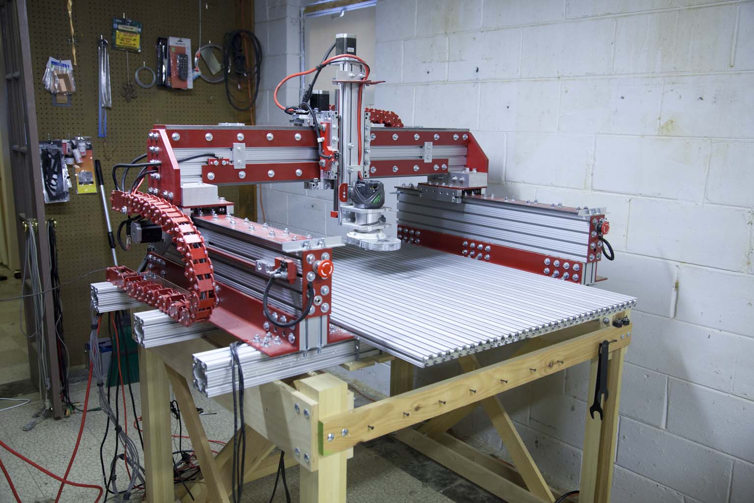
I removed the dust collector hoses and computer. I removed most of the cables from the machine.
Step 2 - Remove Dragon Cables
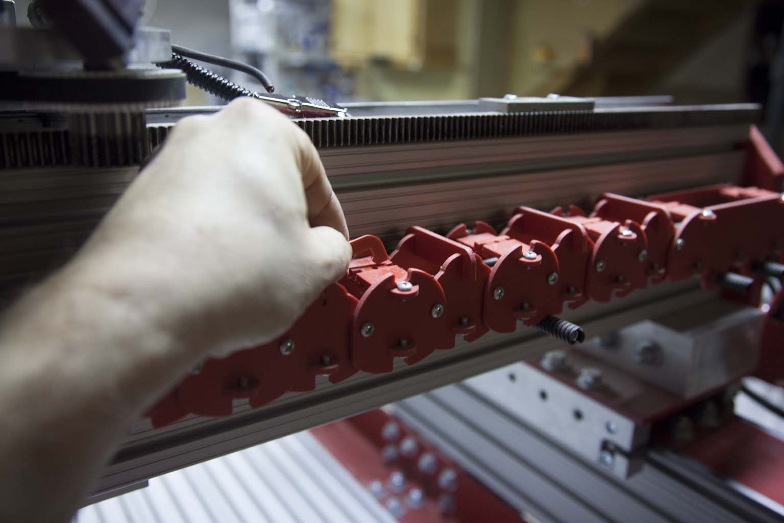
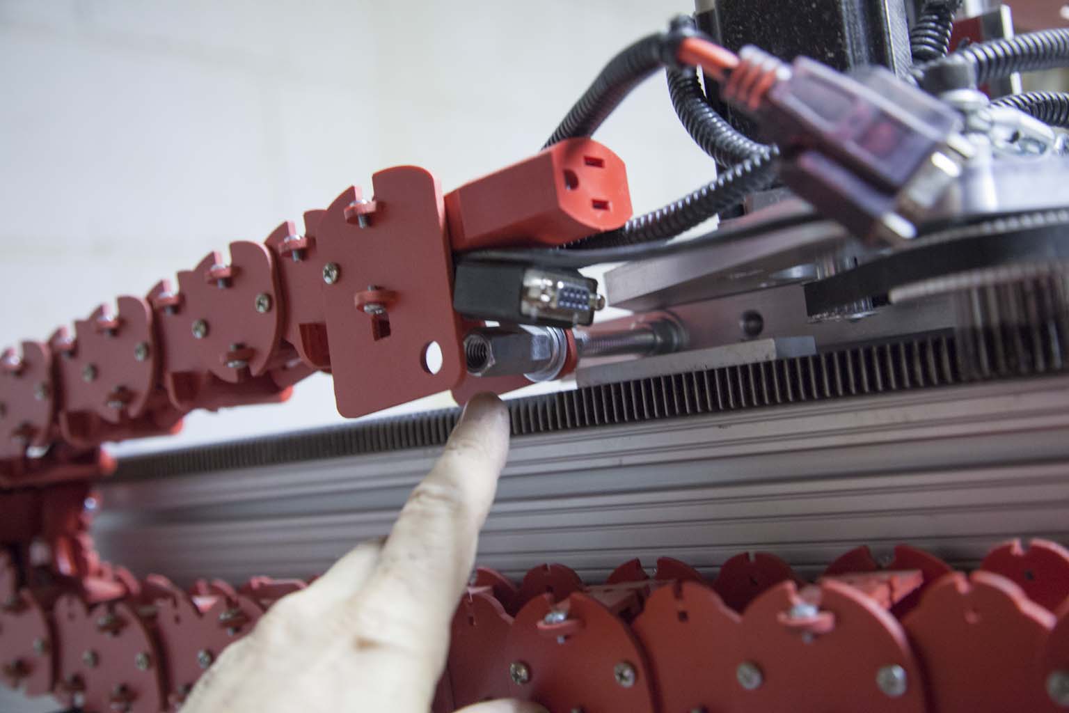
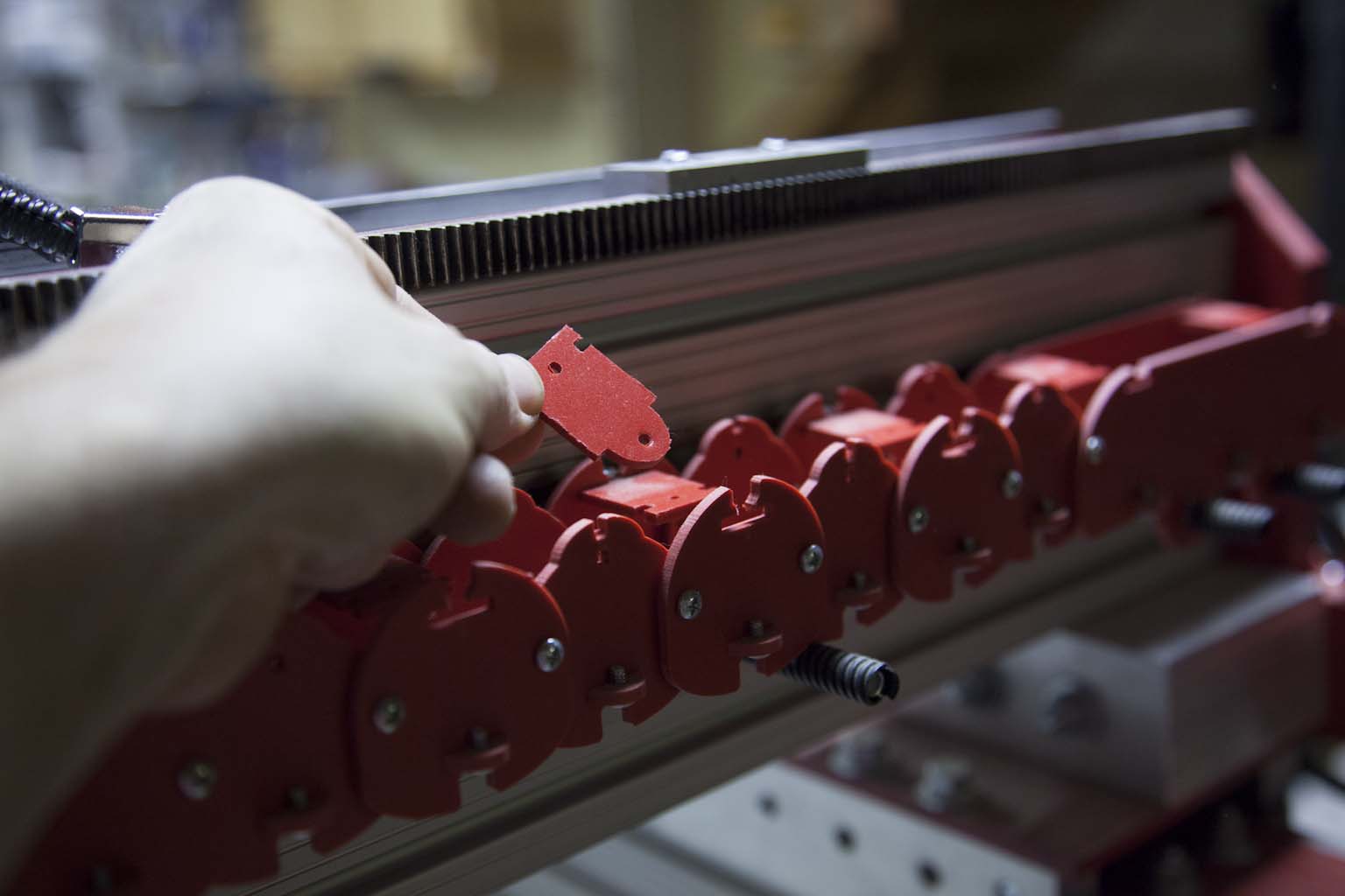
I removed the dragon cables, trying to keep them as intact as possible. I also removed the router from the machine.
Step 3 - Remove Upgrades
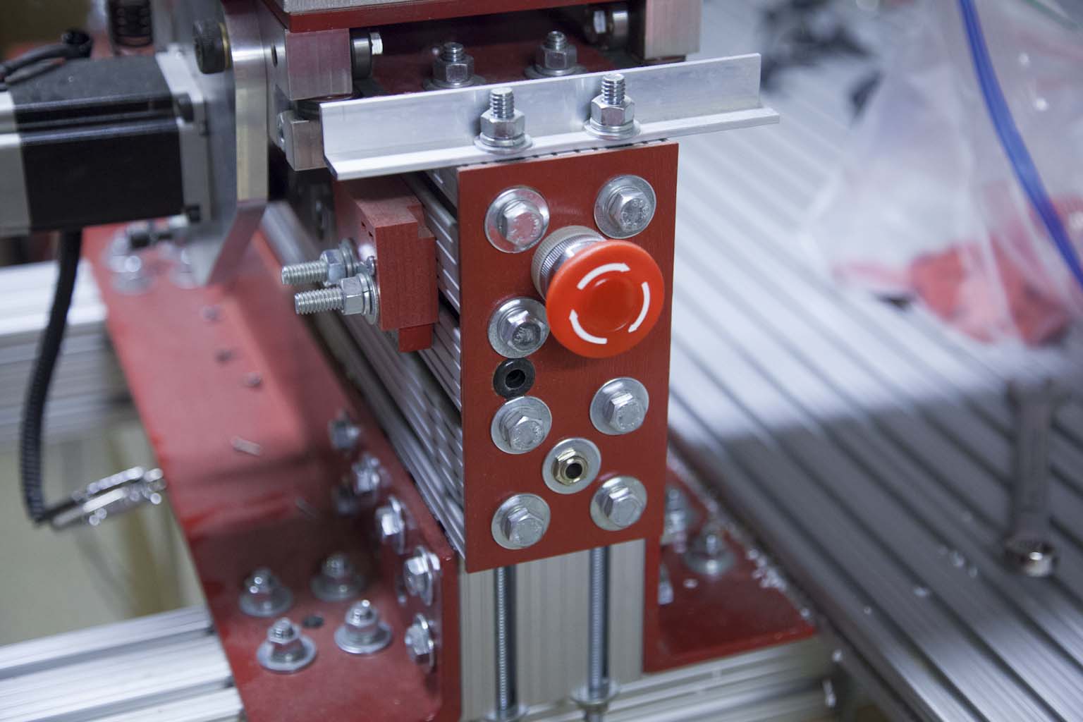
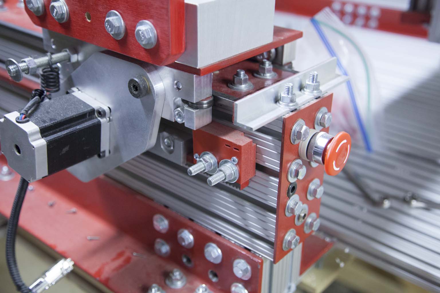
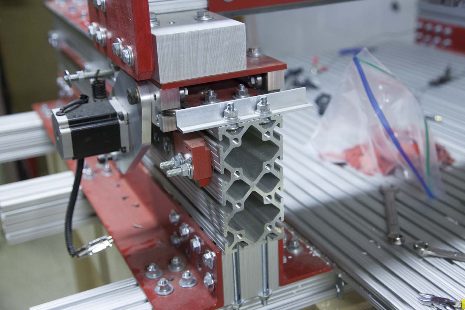
I removed the homing switch, Estop, and probe upgrades and all the wiring associated with them.
Step 4 - Remove R&P drives
I removed all the Rack and Pinion Drives.
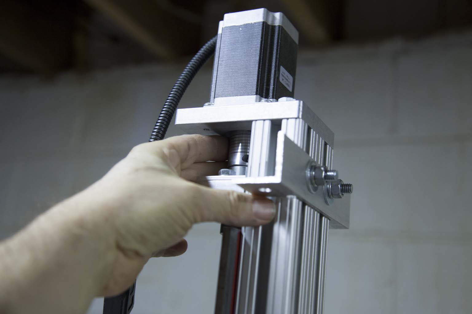
Step 5 - Remove Z-axis
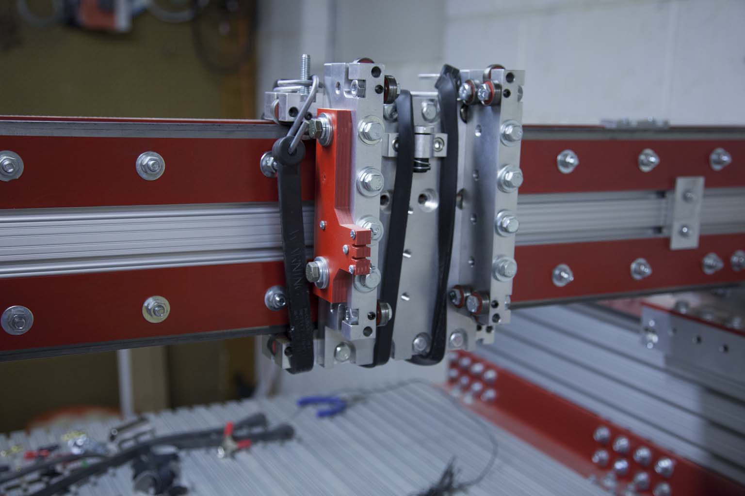
I removed the Z-axis from the machine. I also used some bungee cords to keep the X-axis carriage from moving around.
Step 6 - Remove Gantry Stops
I removed the gantry stop blocks. This must be done so you can slide the carriage off the machine.
Step 7 - Remove Gantry
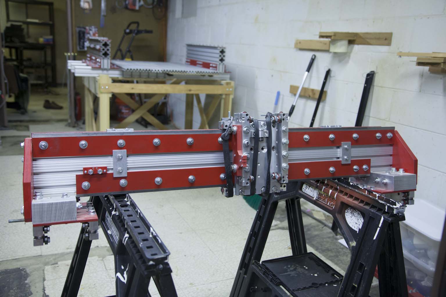
I removed the gantry and placed it out of the way on two saw horses. Note that it will take at least two people to move the gantry from the machine. The 30" gantry weighs 94lbs. The 50" gantry is close to 160lbs.
We simply pushed it forward until it disengaged from the Y-axis rails.
Note that one person can remove the gantry if you have a shop crane.
Step 8 - Remove Table
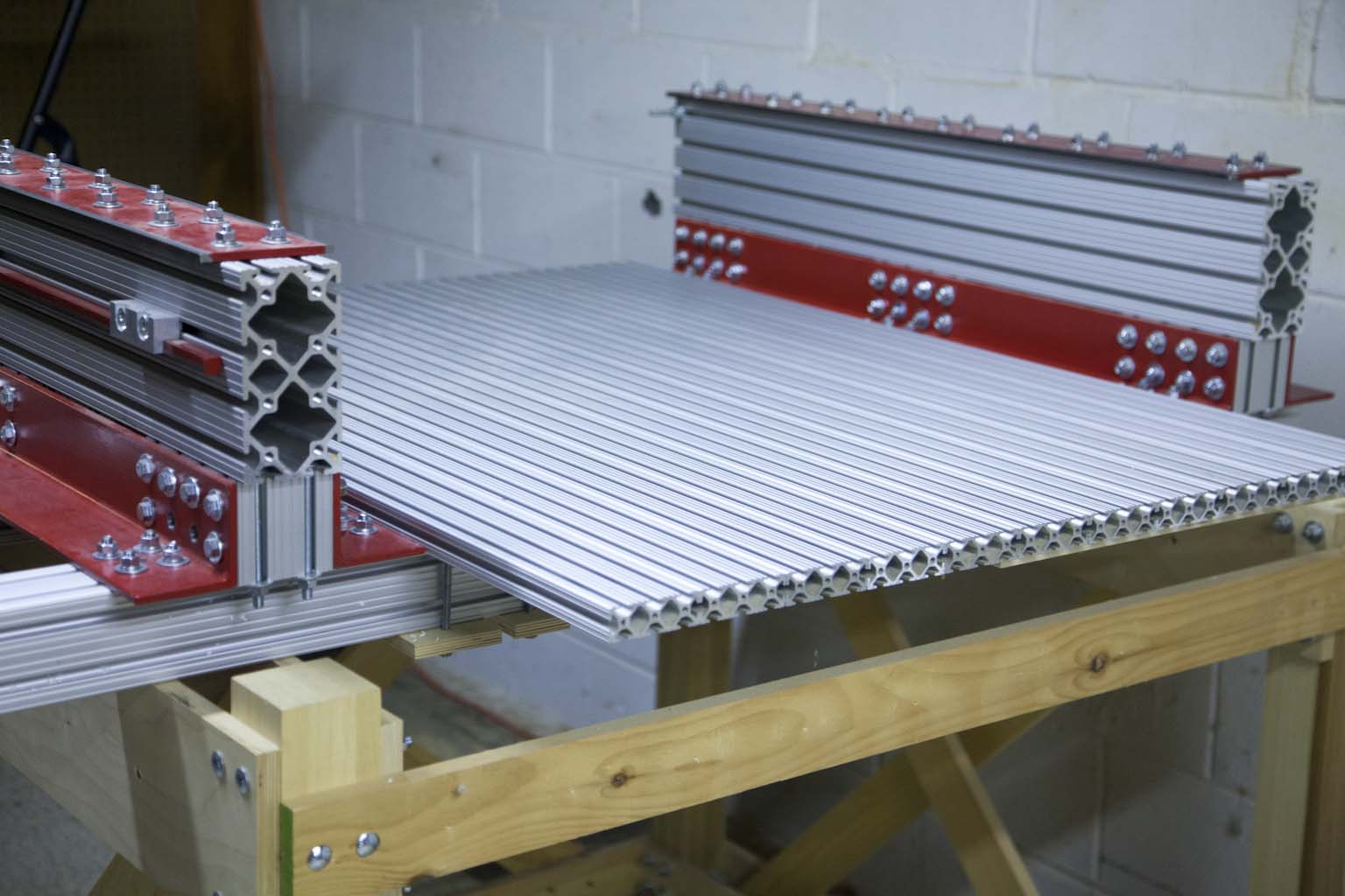
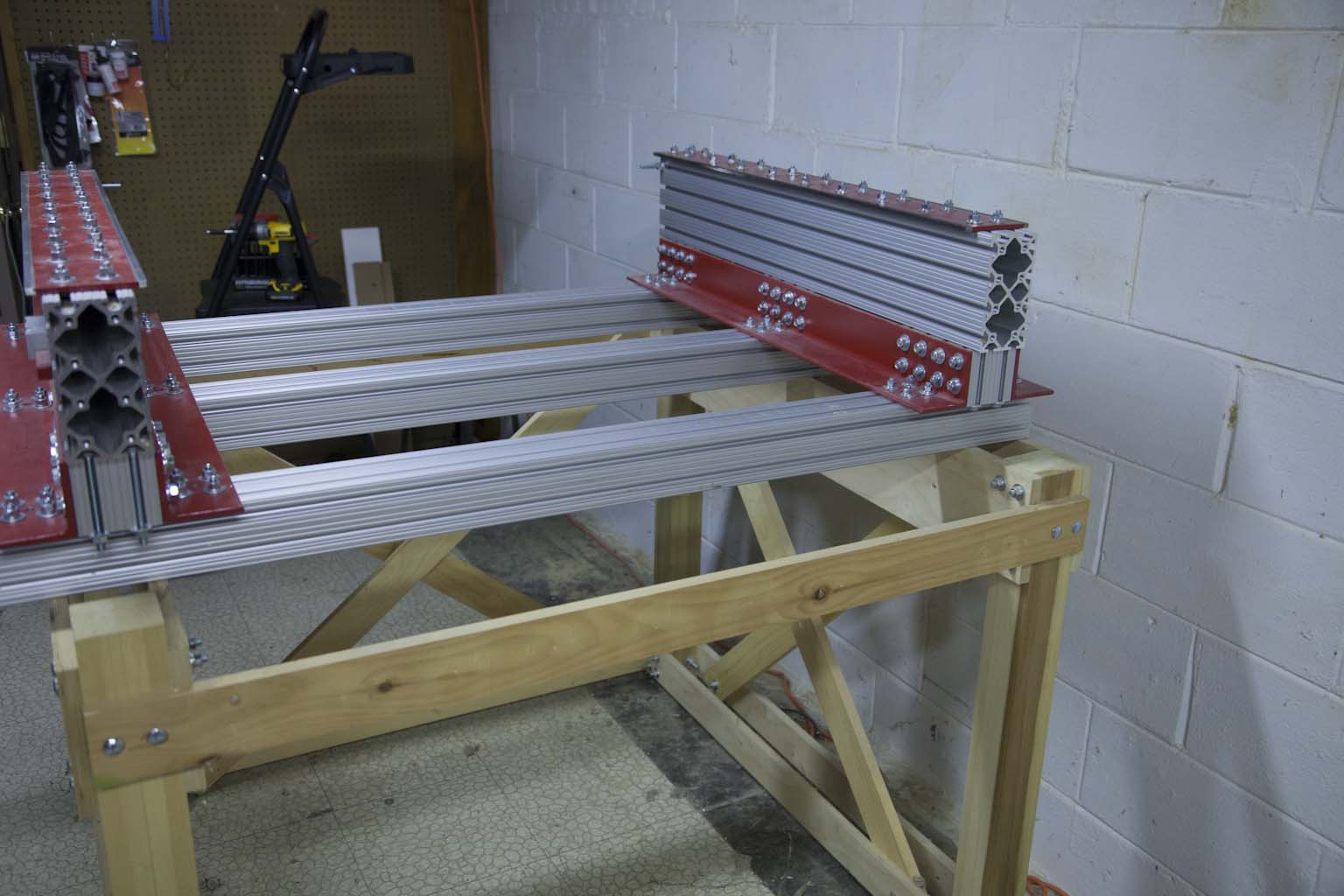
Next, I removed the table. This was done strictly to remove weight from the main frame. The table for the 30x27 build weighs 65lbs.
Note that this table has a removable insert and is not the stock build.
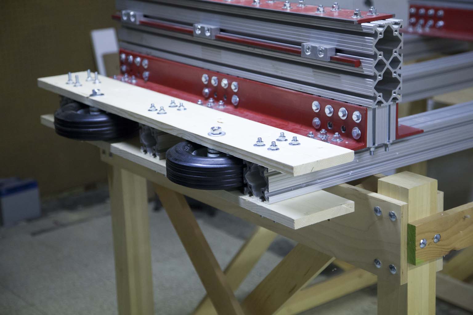
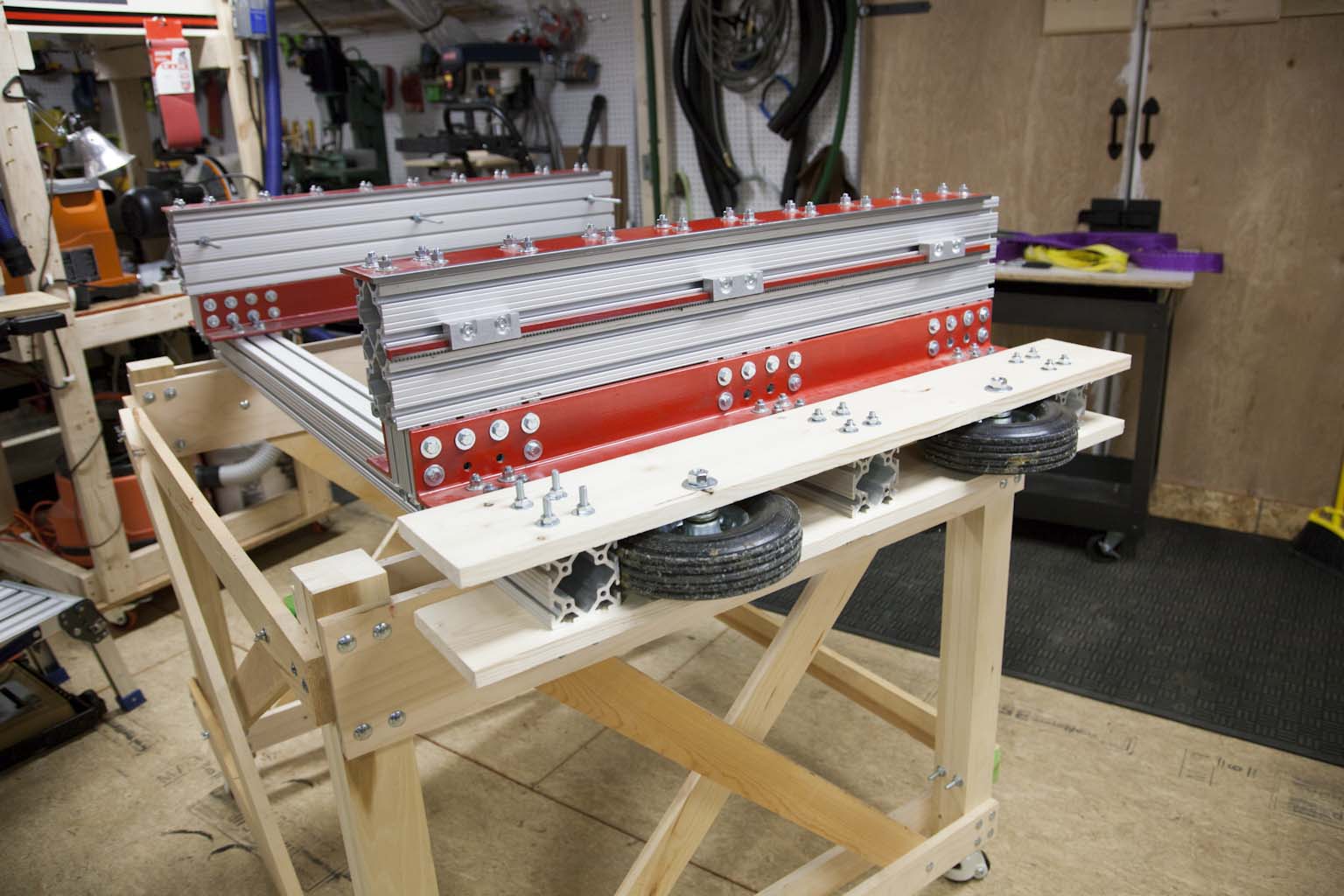
Step 9 - Add Moving Wheels
A little history. The 30x27 build was the original build size of the KRMx02. It was designed with the idea of adding a set of wheels to the side to facilitate moving the machine to various trade shows.
Later I realized the machine was just too much to move on a regular basis. It was designed for rigidity not portability.
I then scaled the machine to the other build sizes, 18x14, 50x27, 50x50, 50x102.
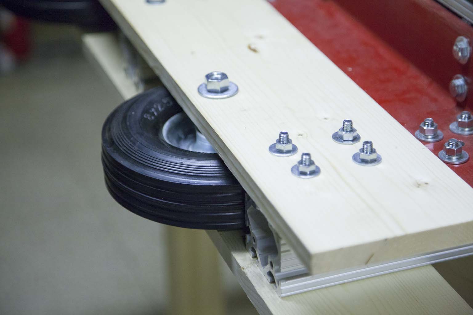
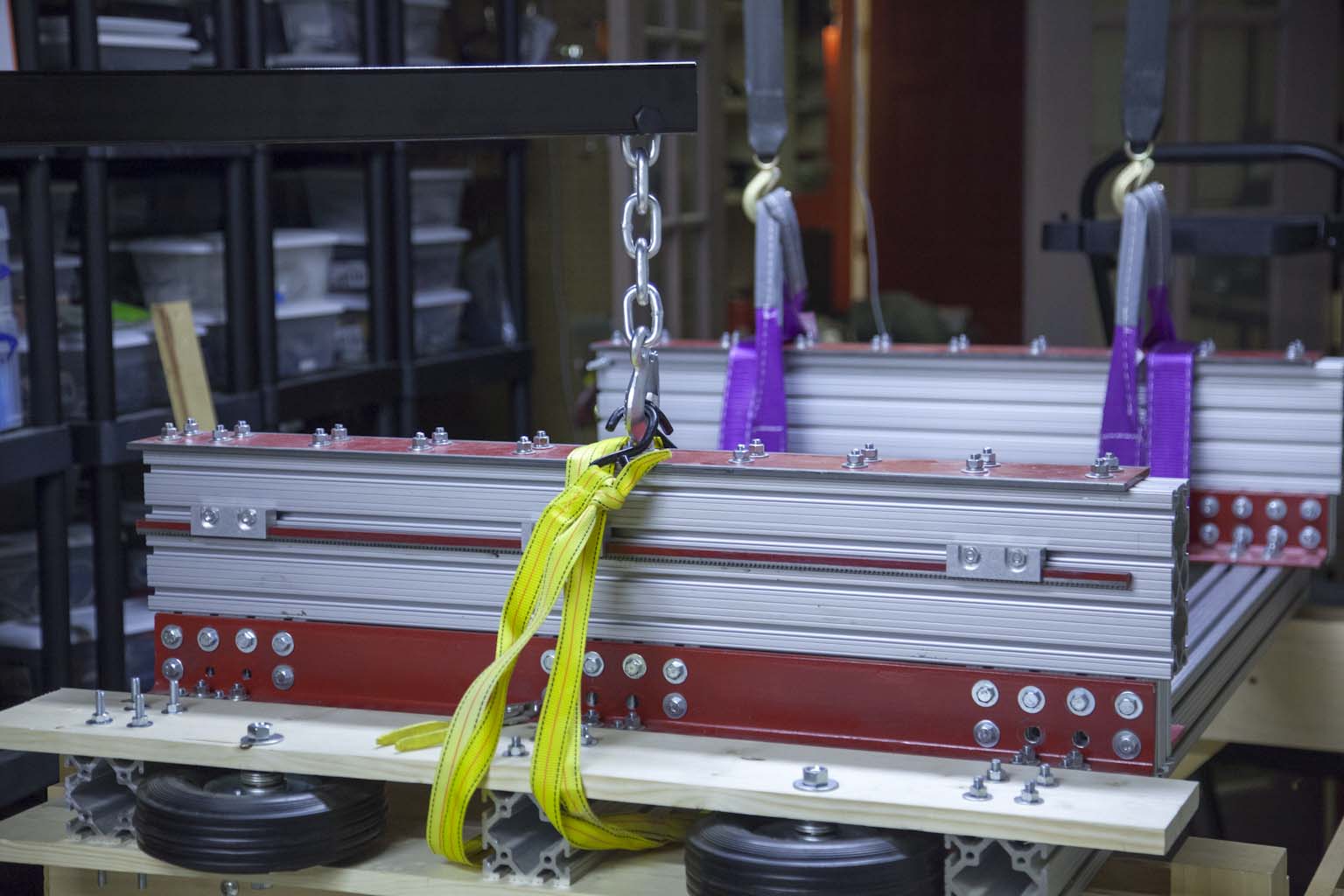
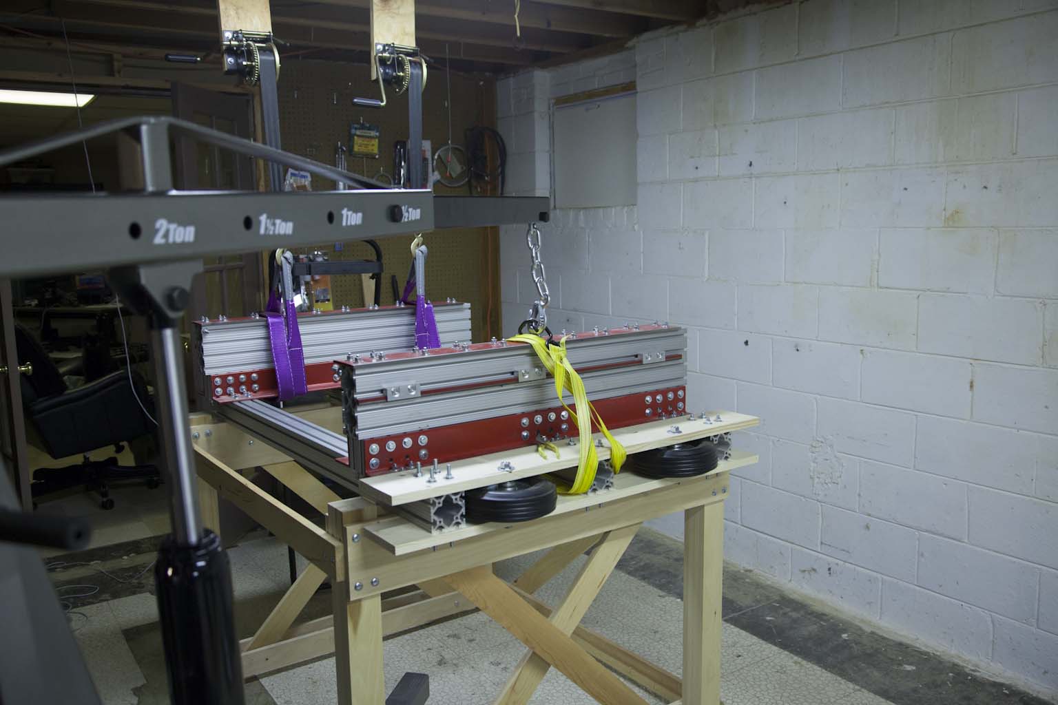
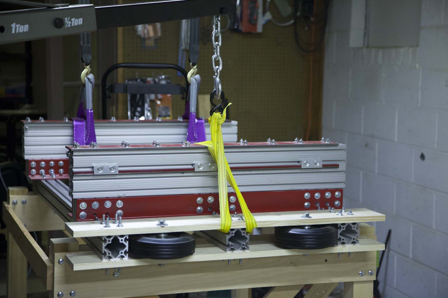
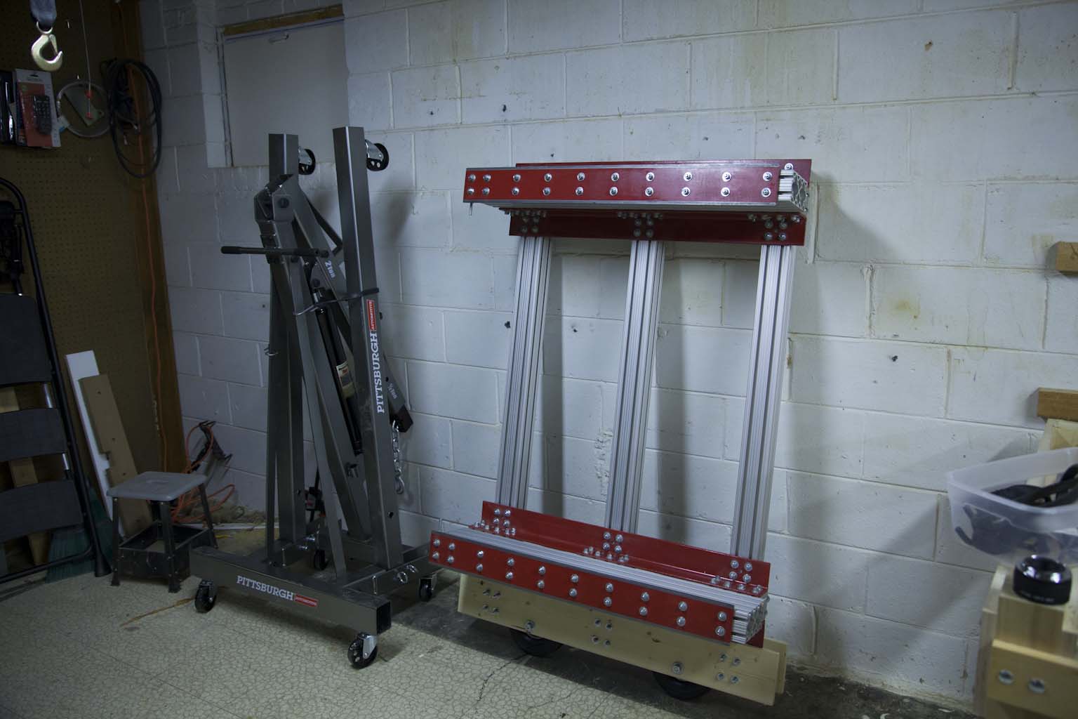
The wheel supports are simply two 1x6" attached to each side of the cross beams with wheels mounted between them. The frame shown here weighs in at 153lbs.
Step 10 - Position the Frame on the Wheels
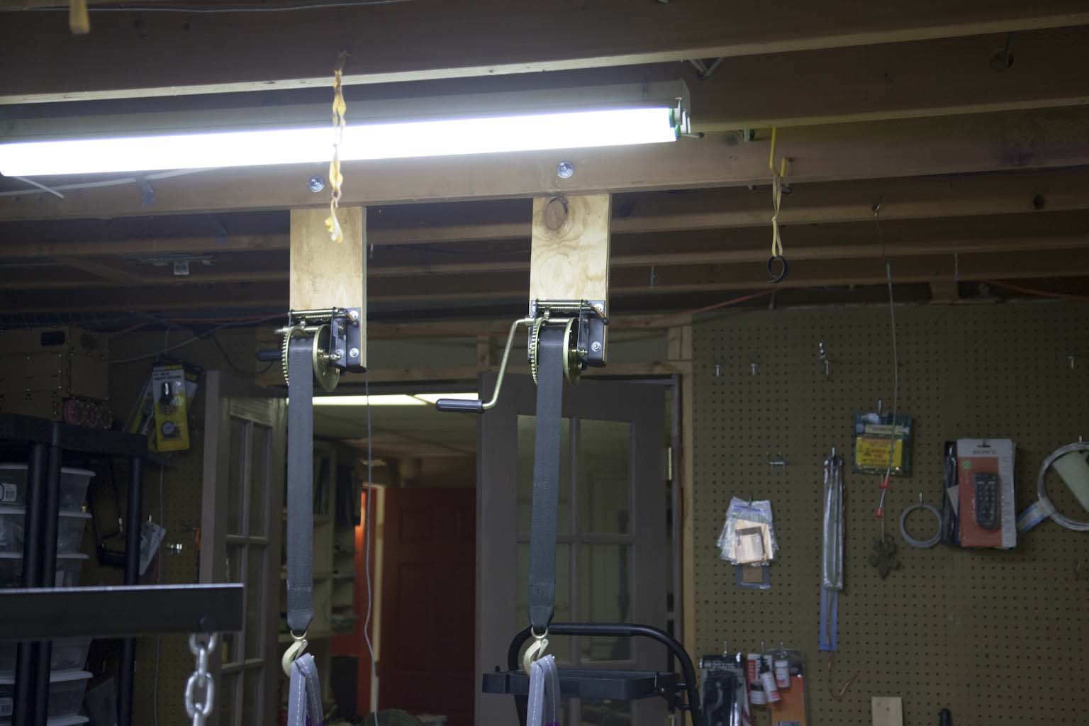
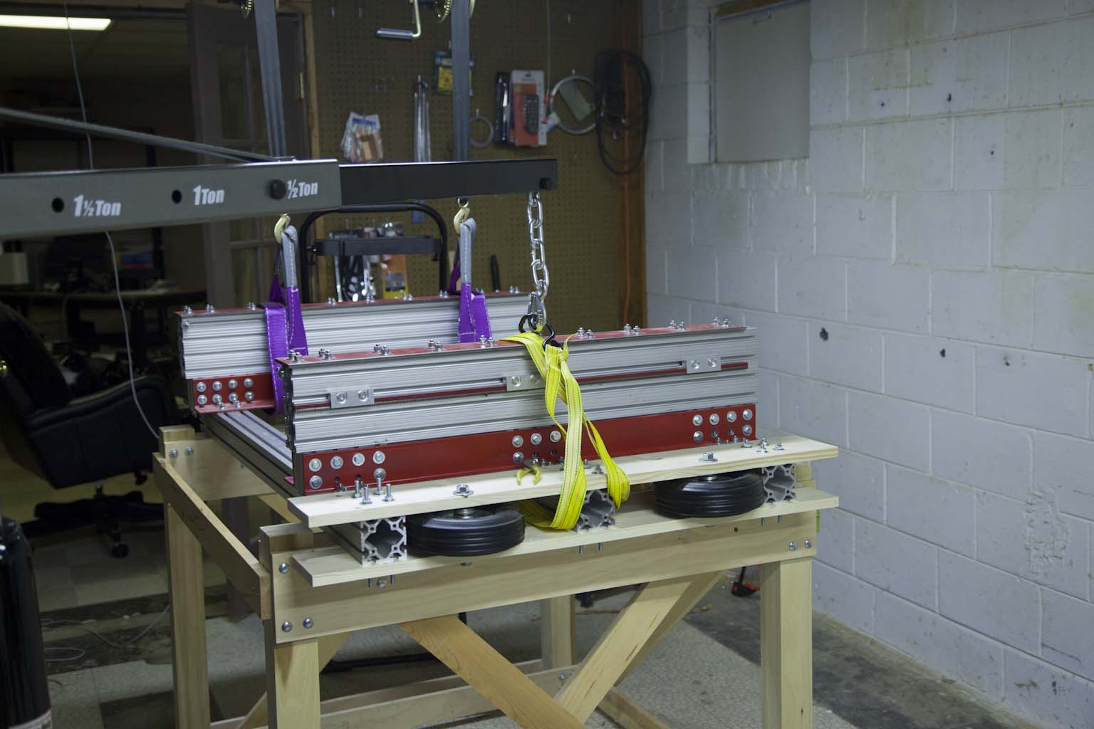
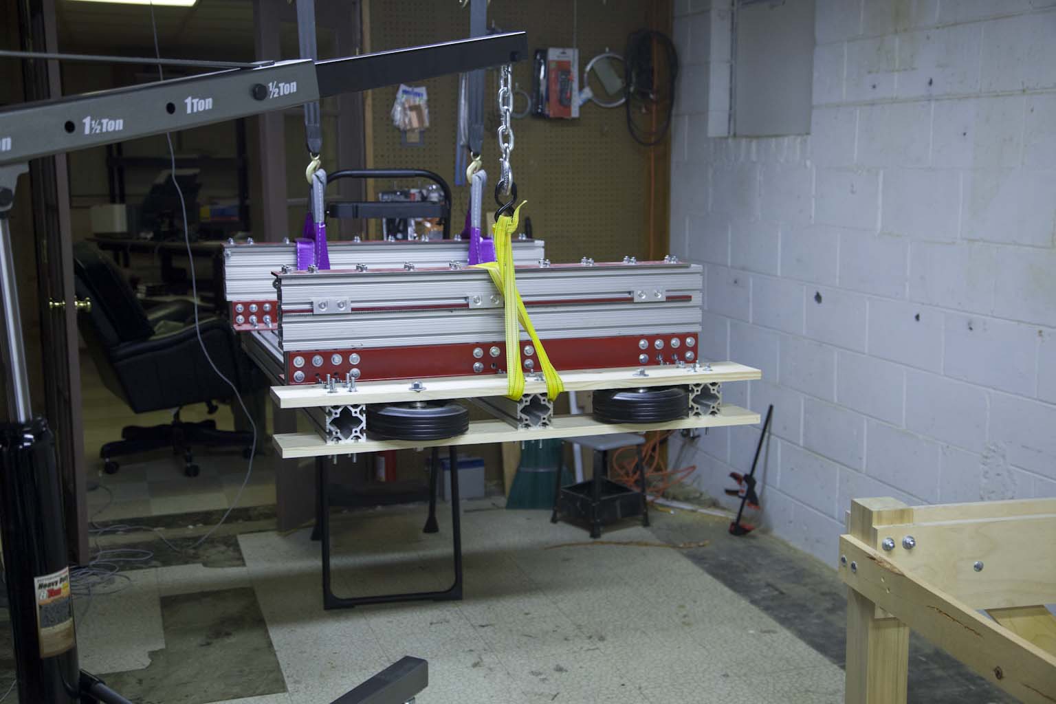
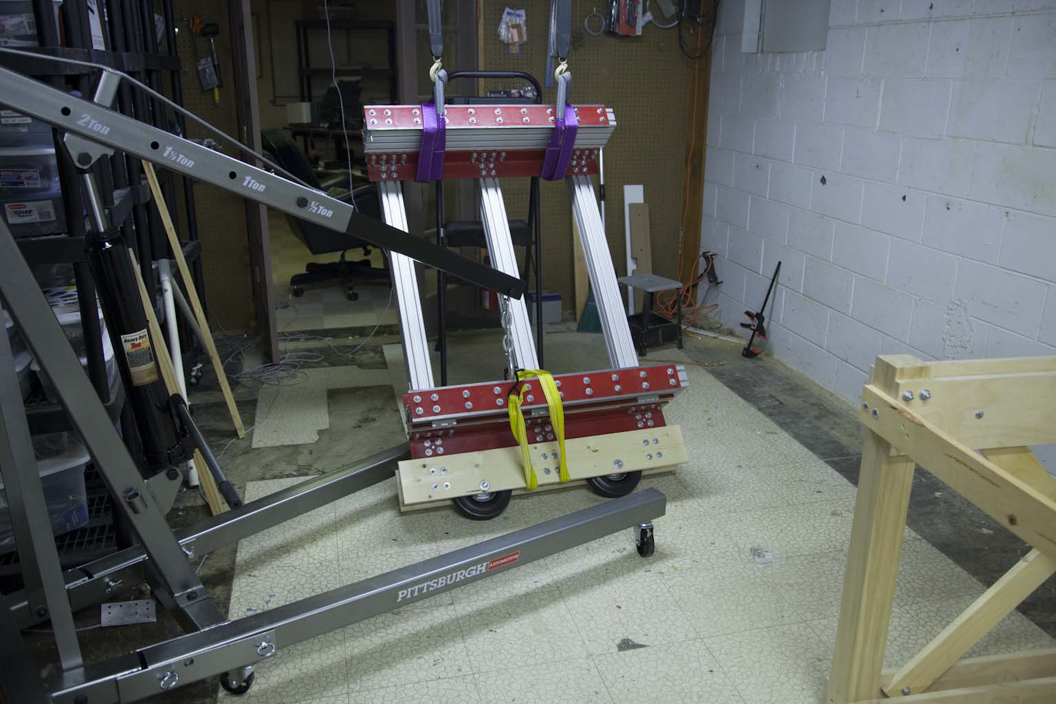
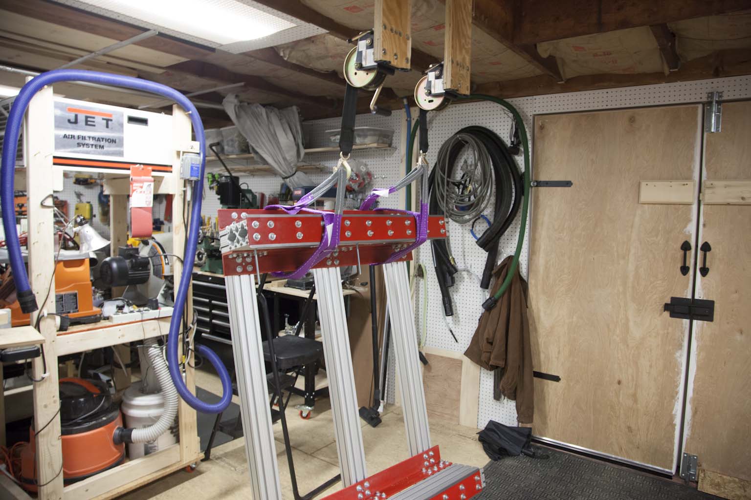
This could be done a couple ways. Here I used two hand winches to lift one end of the frame just off the base.
I used a shop crane to lift the other end. I then removed the base and lowered the wheels to the ground. At that point it was easy to balance the frame on the wheels.
Step 11 - Prepare Stand
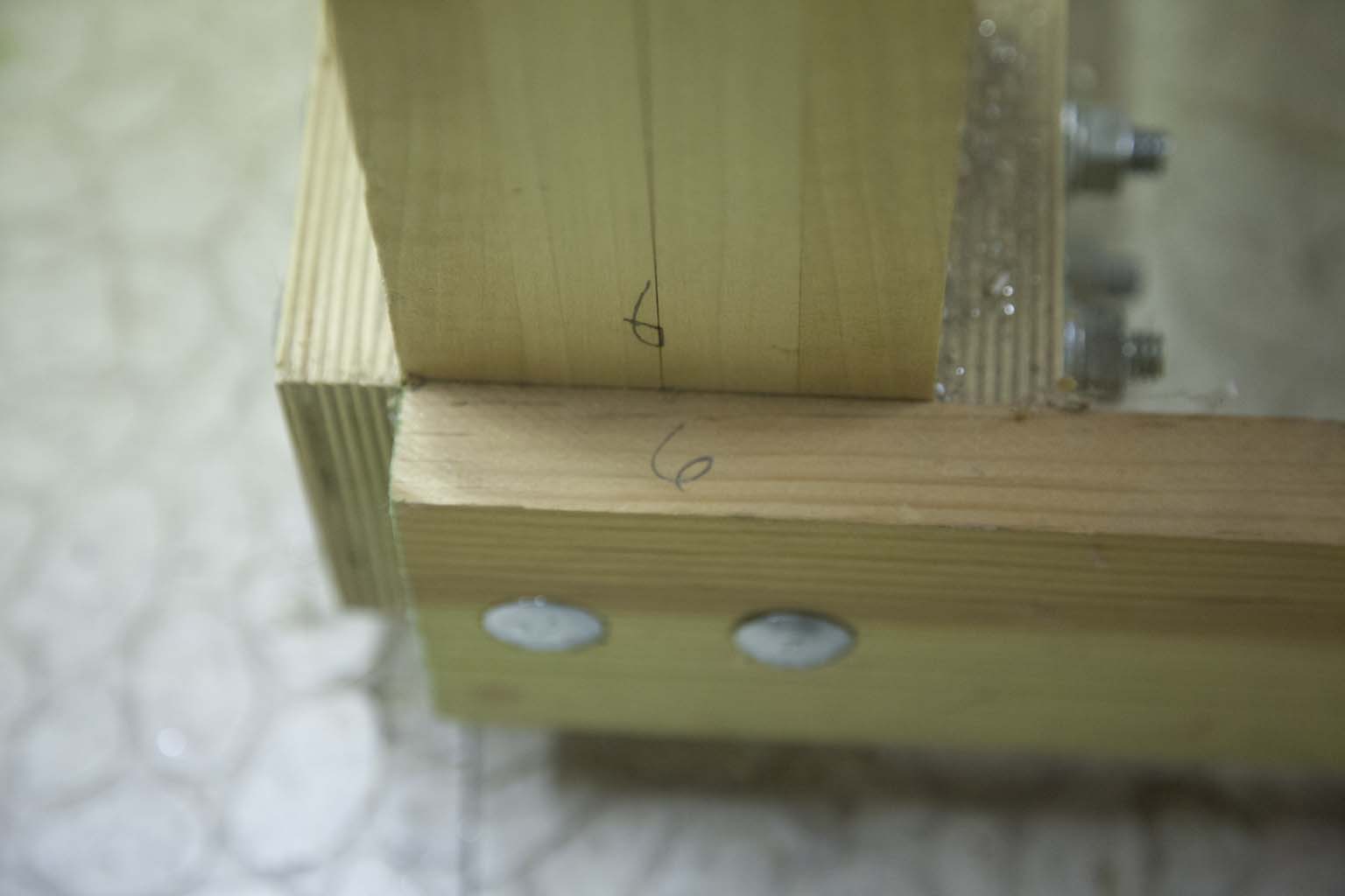
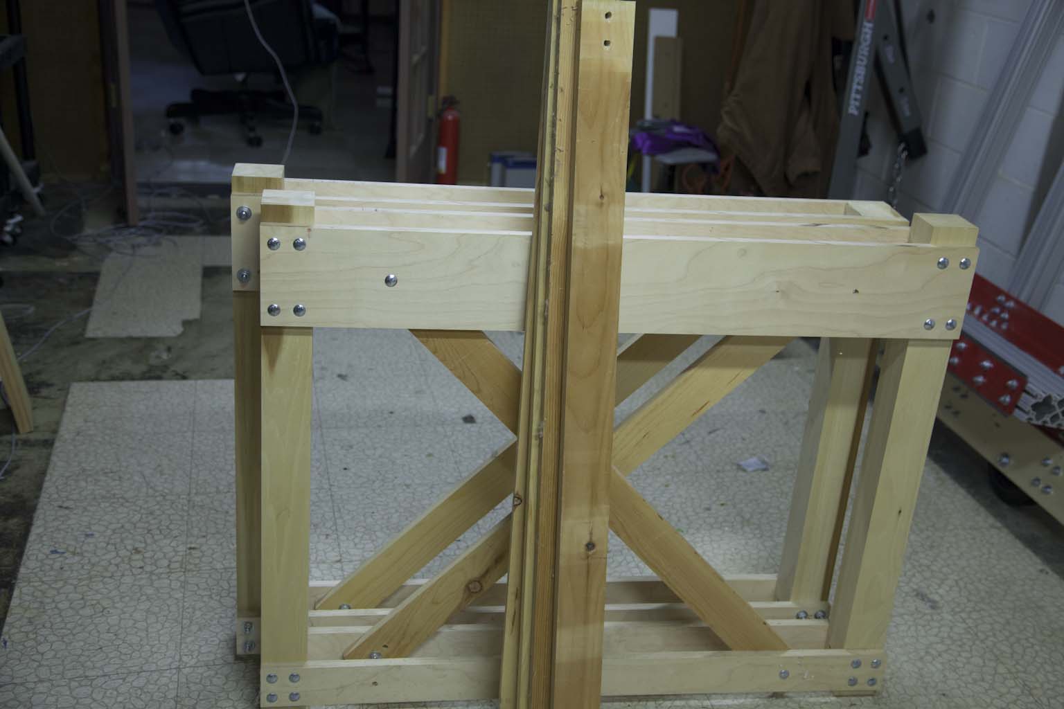
The stand is easy. Just remove the four stretchers. Be sure to mark the parts as shown show you can reassemble them.
Step 12 - Move the Machine
Not much to say here. Just relocate all the parts to the new location.
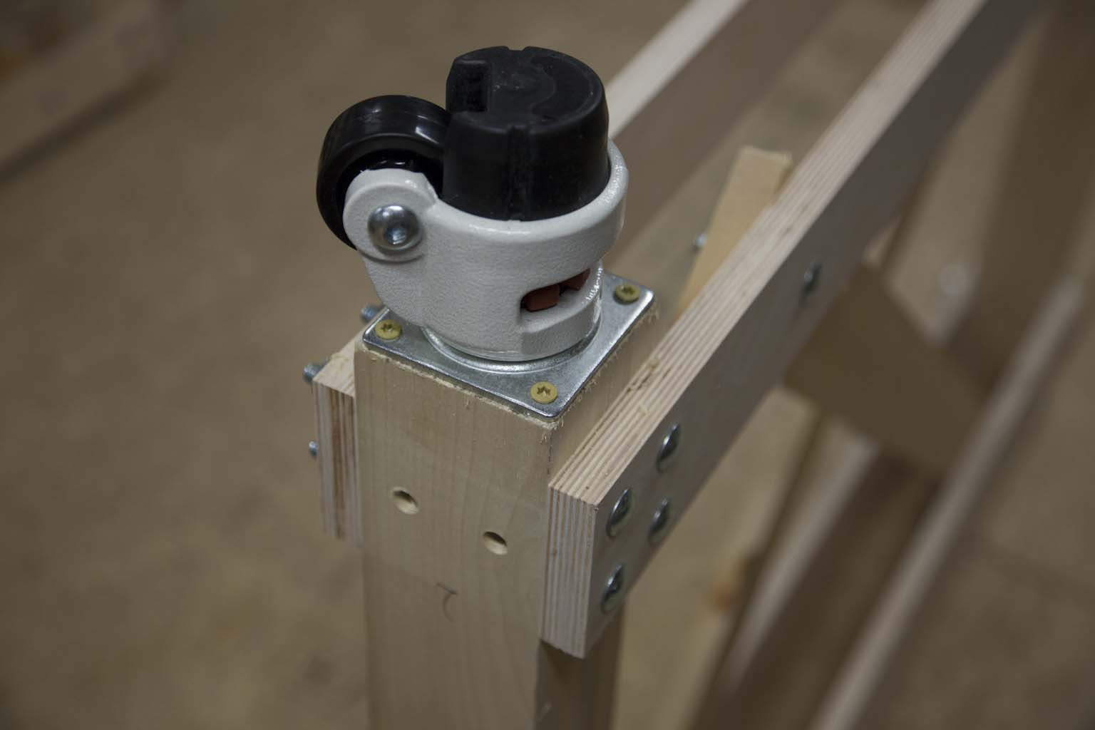
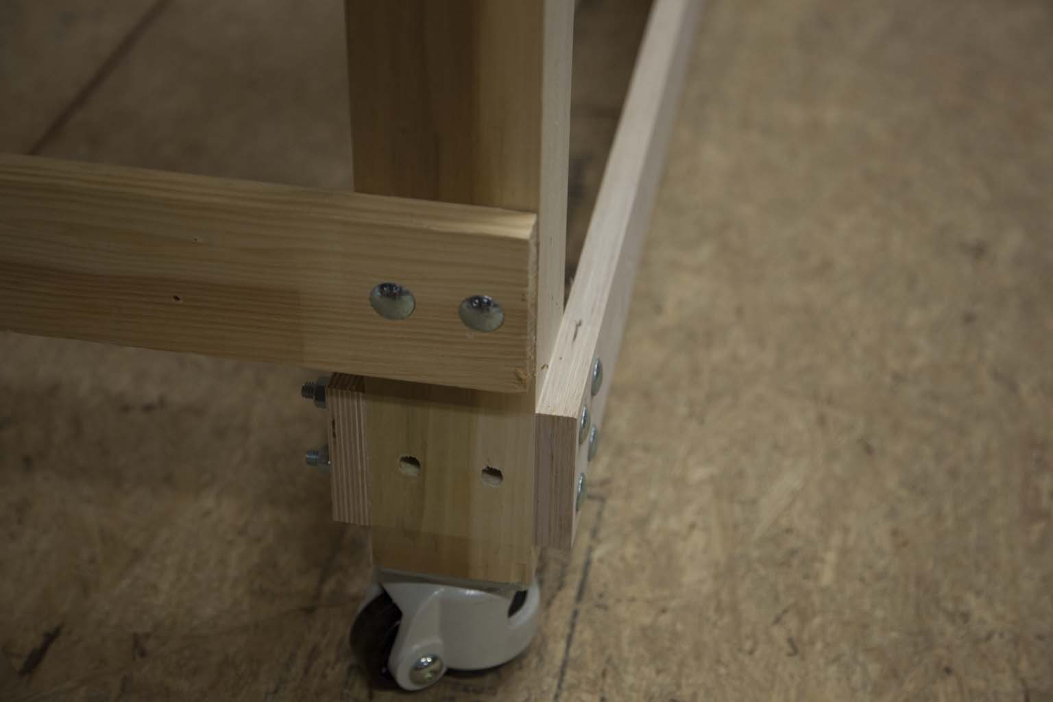
Step 13 - Add Wheels to Table
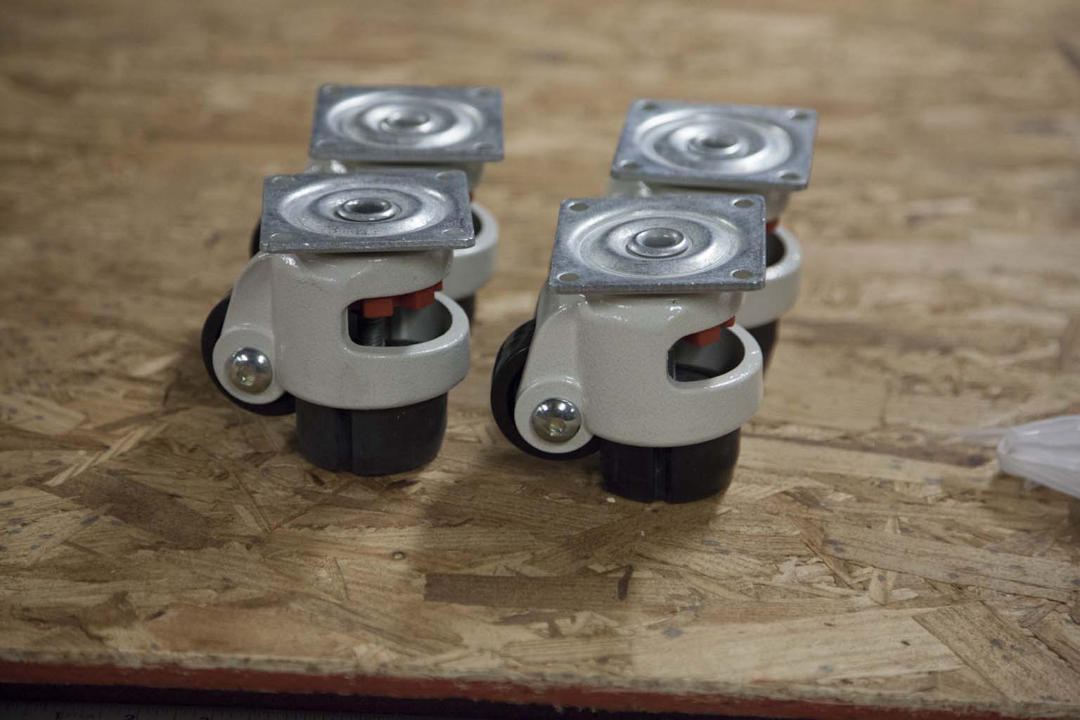
A machine without wheels will always be more stable and vibrates less than one with wheels. That said, I have a rule in the new shop. Every thing must be mobile.
This is so I can reconfigure the shop as needed for new projects and books.
Get the thumb wheel casters here:
Get the ratchet casters here:
Step 14 - Reassemble the Table
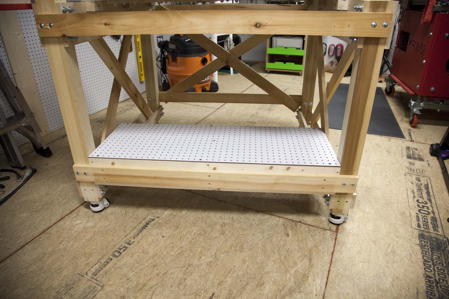
I made a couple design changes when I reassembled the stand. First I raised the bottom stretcher so that it was 8-1/2" off the ground. I did this to give the feet on my crane clearance to move under the stretchers.
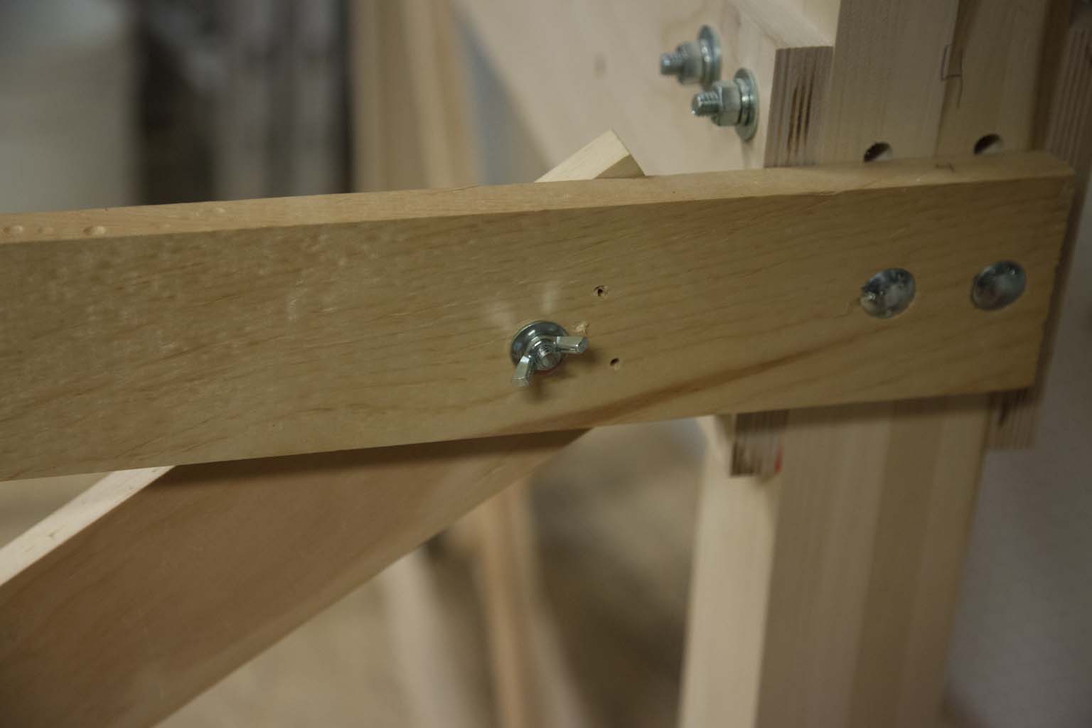
Next I added wing nuts to the rear stretcher cross braces so they could be removed as needed or access.
Step 15 - Set Frame on Table
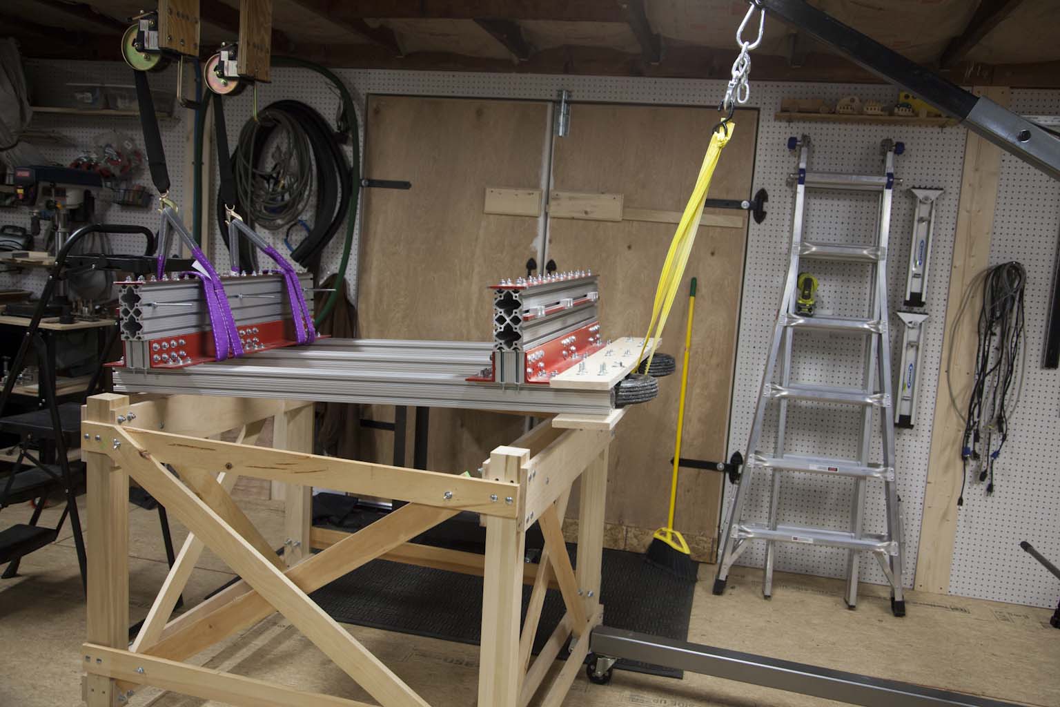
Setting the from on the table was pretty much the opposite of what I did in step 10.
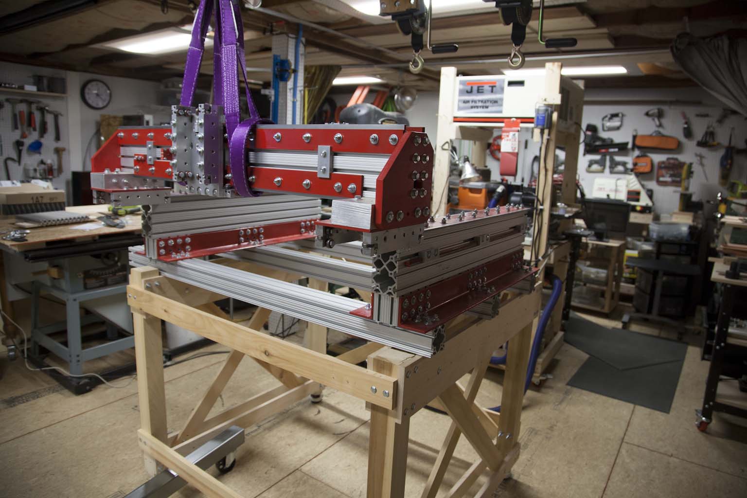
I attached two hand wenches to one end of the CNC frame and a shop crane to the other. The whole thing was cranked up as needed to slide the stand in place.
Once in place I removed the wheels and supports.
Step 16 - Add Guides to Frame
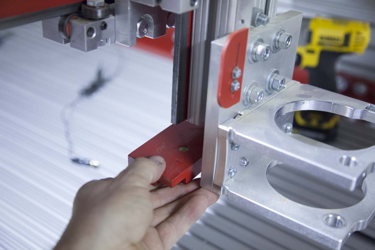
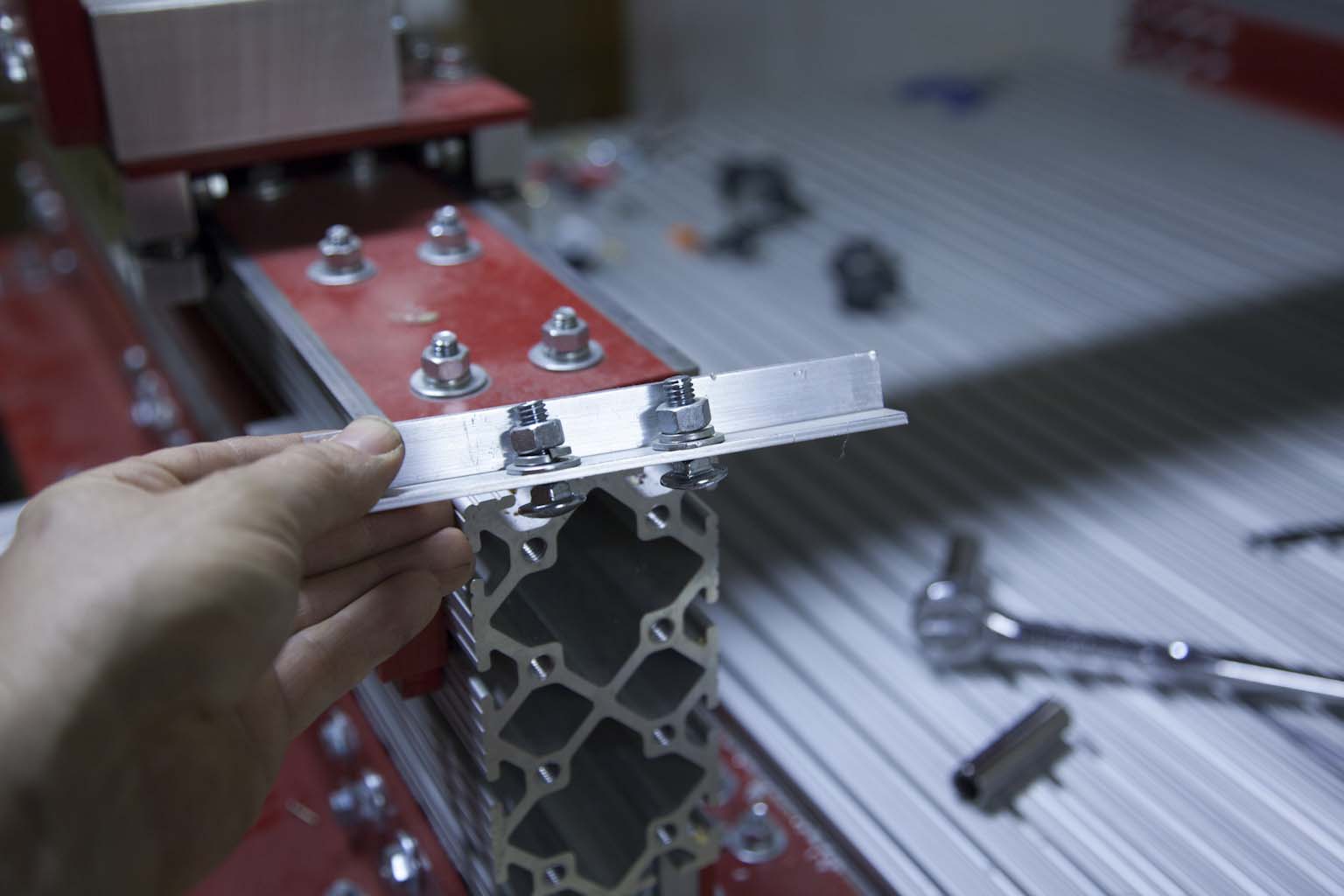
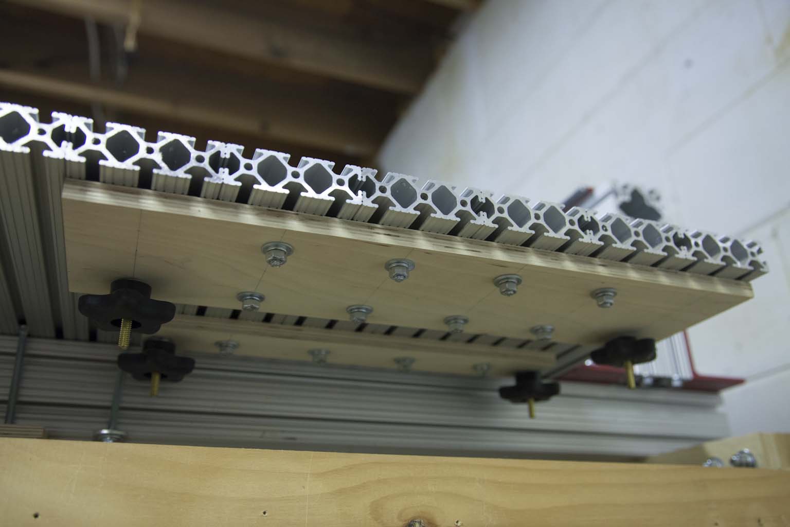
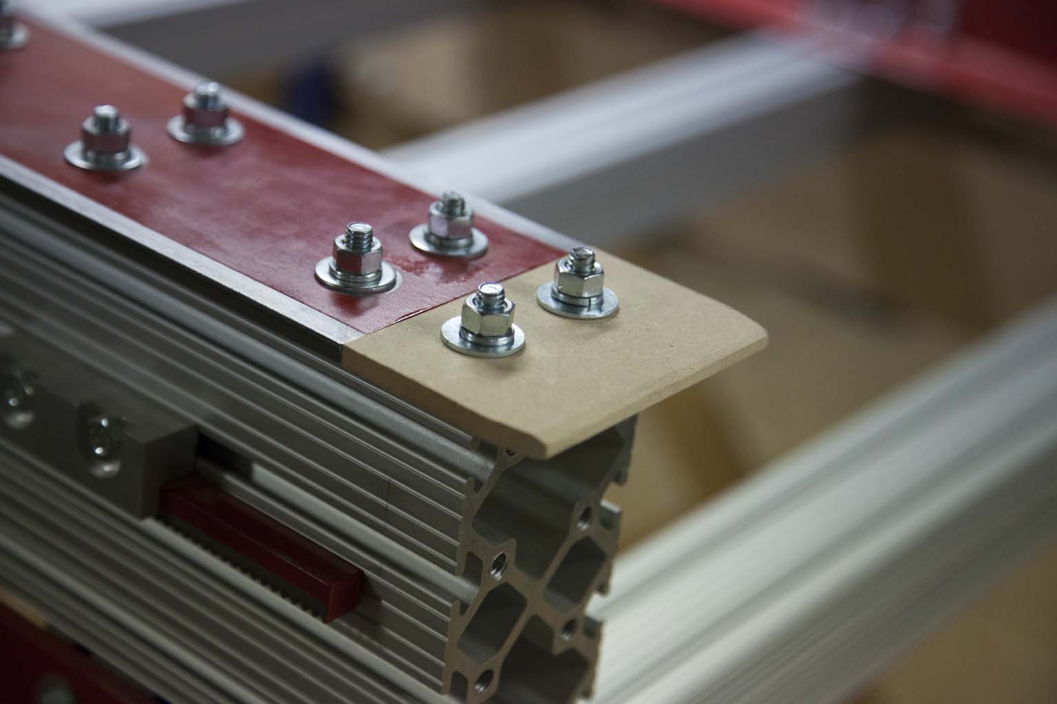
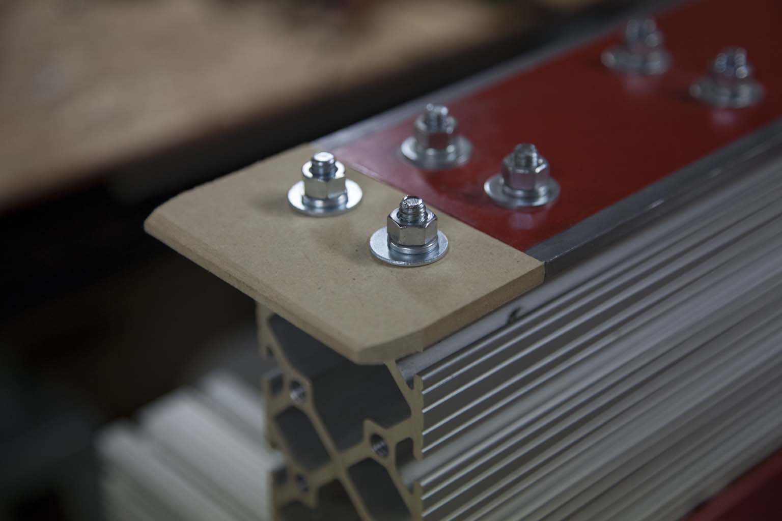
To faclitate aligning the gantry with the rails, I added two small MDF guide blocks to the front of the Y-beams.
They have tapered ends and will allow the gantry to slide into position without having to loosen the bearings on the carriages.
Step 17 - Attach Gantry
To attach the gantry to the frame I used the shop crane to hold the gantry in place while I slid it over the guides.
It worked perfectly.
Step 18 - Attach CNC to Stand
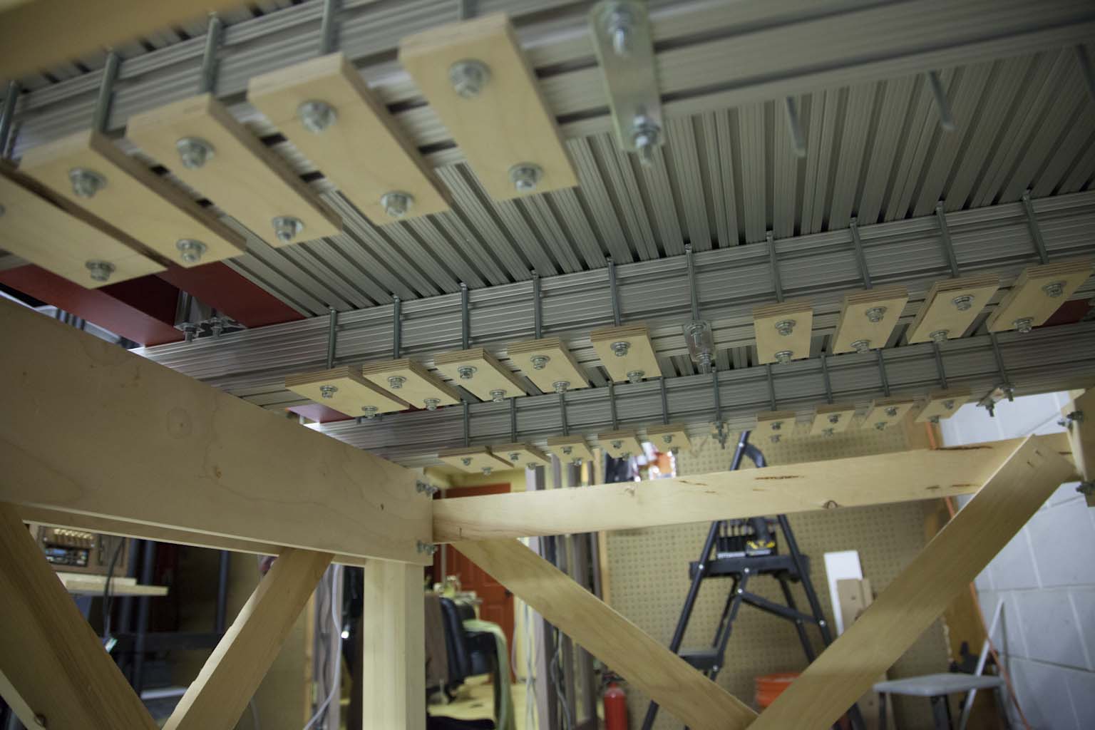
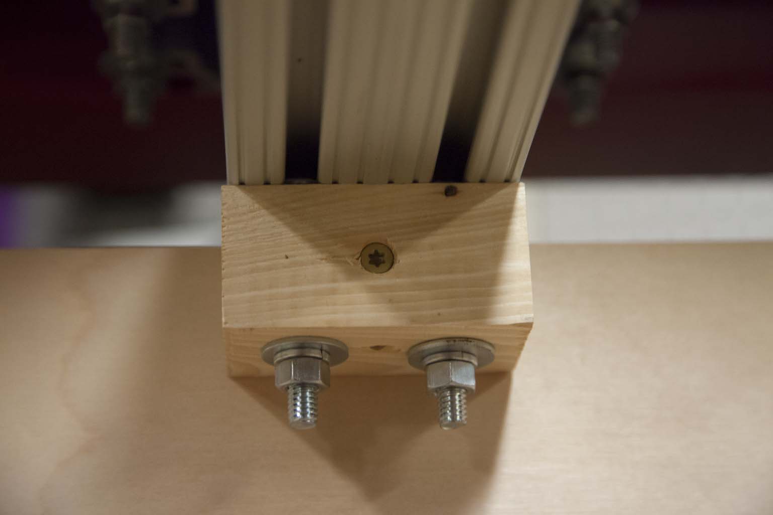
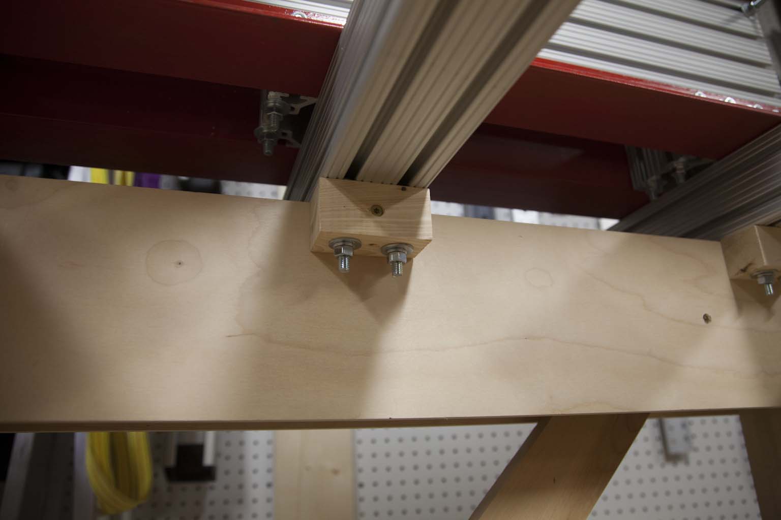
Since the CNC is now mobile I attached each of the cross beams to the stand as shown here.
I used a small 3" x 1.5" block with holes drilled to accept carriage bolts mounted to the cross beams. The blocks were then attached to the stand with deck screws.
Step 19 - Add Shelf to Stand
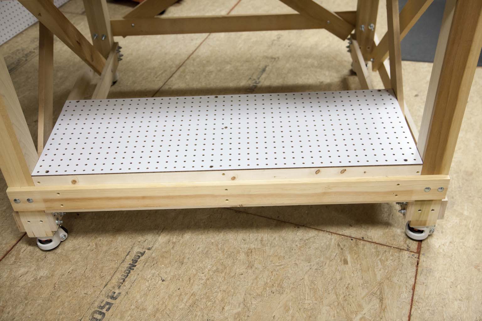
Another change I made was to add a shelf to the front of the stand.
This be used to hold a computer/controller.
Final Hookup
I reattached the table, dragon cables, Z-axis, cables, and computer to the CNC.
The PC/Controller is now mounted on the front shelf.
I added a side table for the monitor mount and a hose guide for the dust collector.
How does it all work
Every thing went perfect. I had no alignment issues. The machine is up and running once again in its new home.
Recommendations
Hanging Crane Scale
This little beauty hangs between the crane and the object you are lifting. It can be set to alarm if you lift over a preset weight. It is good up to 1100Lbs.
Get it here:
Get the thumb wheel casters here:
Get the ratchet casters here:


