
I build several CNC based machines every year. While I can pull out one of my full 4 channel controller assemblies, that's a little more effort than it is worth if I just need to do a simple drive test.
This one lets me do a real quick check on a single axis drive system.
I single knob controls the stepper motor speed. A button enables or disables the motor driver. A second button controls the motor direction. It has plenty of power to control motors that require up to 4 Amps per phase.
Major Components
There are three major components that make up the stepper motor tester.
Power Supply
The tester uses a 24v 15Amp power supply. While a 24v 7Amp power supply would work, the cost and availability for this one gives you your best bang for the buck.
You can find one here:
Pulse Generator
To create the pulses needed to move the stepper motor this little pulse generator works like a charm.
It supports:
- Motor Enable
- Step Direction
- Step Pulse
You can pick one up here:
Stepper Motor Driver
To drive the stepper motor you will need a driver like the one shown here. It supports up to 3.5 Amps continuous and 4 Amps peak.
You can set the micro-step rates from 1 to 32 steps.
Get it here:
Assembly
Base
I created a base for the components out of a 3/4" thick melamine coated particle board cut to 11-1/2" x 11-1/2".
I placed two 5/8" holes 6" apart at the rear of the base. These will allow me to hang the testor on my pegboard walls when not in use.
Power Supply Brackets
While you can attach the power supply in a multitude of ways, I elected to mount two 3/4" aluminum angles to the sides of the power supply. They are secured with four M4 machine screws.
Mount Power Supply
I then used some #6 wood screws to attach the power supply to the base. It is mounted close to the right edge and about 1/2" from the front.
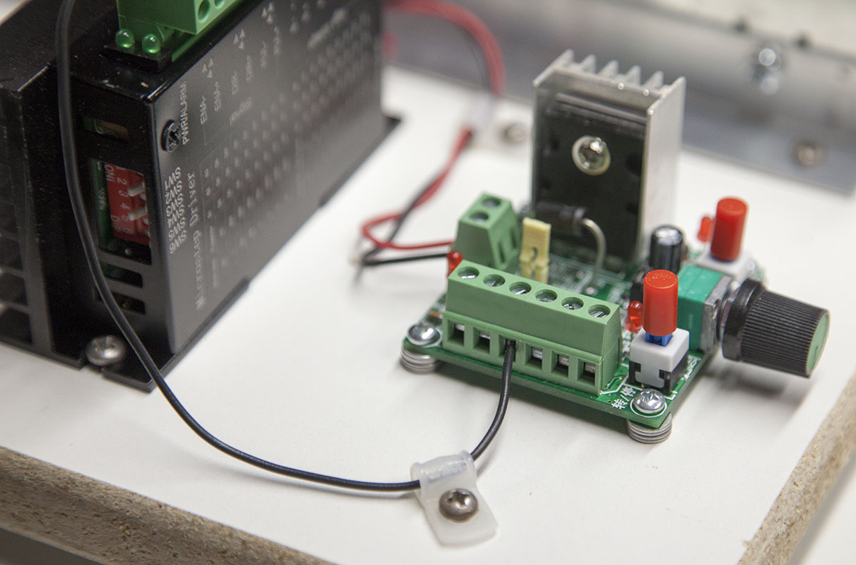
Mount Pulse Generator and Driver
The pulse generator is mounted to the base using some #4 wood screws. I added four #4 washers under each corner to keep the PCB off the surface of the base.
The stepper motor driver is added to the base behind the pulse generator.
Wiring
AC Power
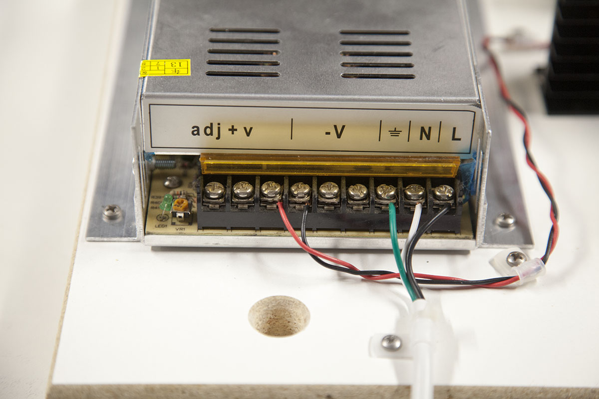
I attached a grounded power cord to the three terminals marked Ground, Neutral, and Line.
Be sure to secure the cord with a cable clamp.
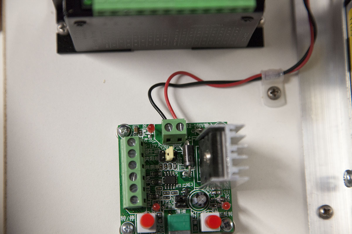
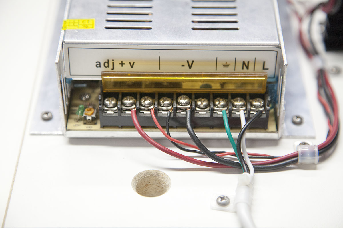
Pulse Generator Power
Wire the power to the pulse generator as shown here.
Be sure to use some cable clamps to secure the wires.
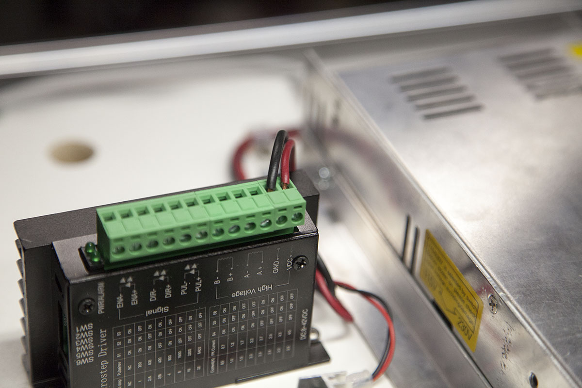
Driver Power
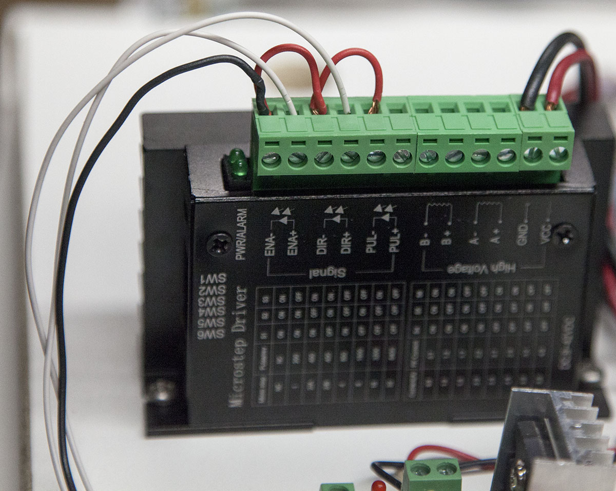
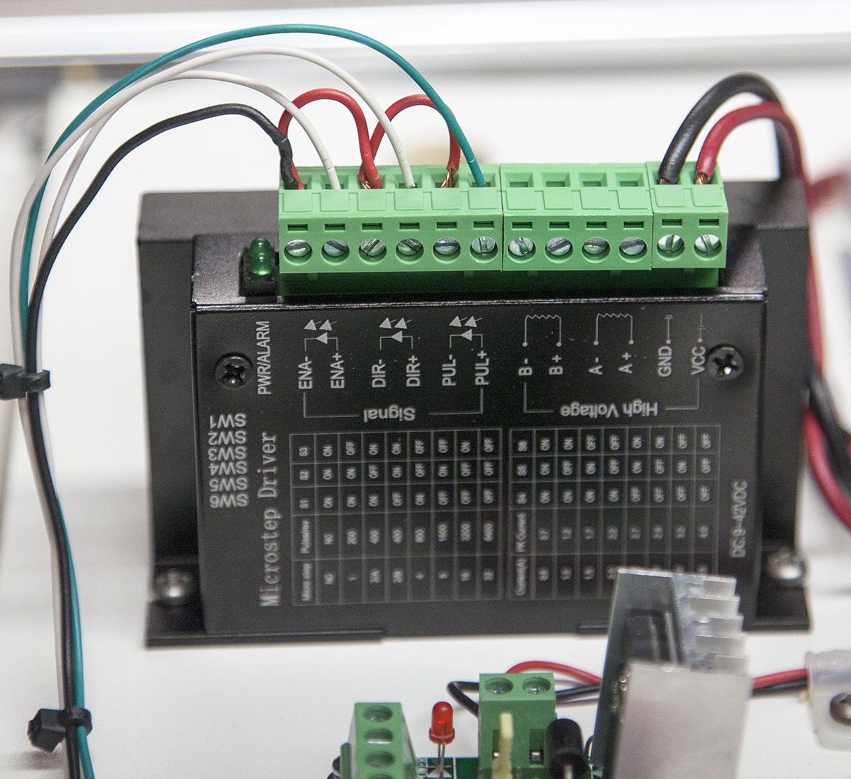
Wire the power to the stepper motor driver as shown here.
Be sure to use some cable clamps to secure the wires.
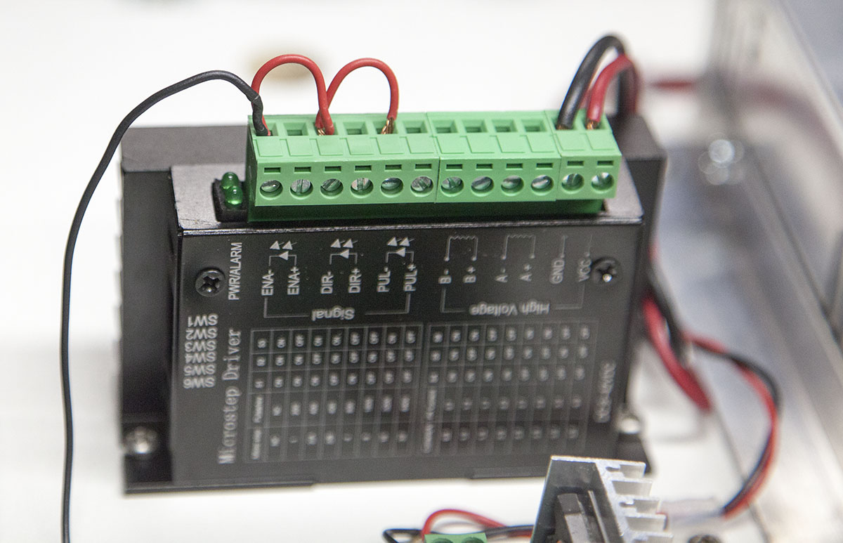
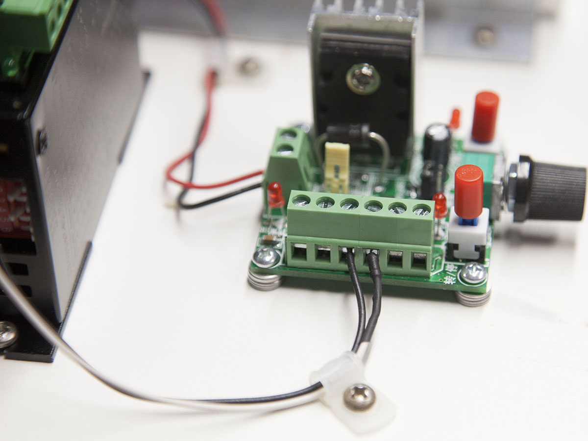
Signal Common
Add a jumper between the ENA-, DIR-, and PUL-. Run a wire from these jumpers to the common cathode terminal on the pulse generator as shown.

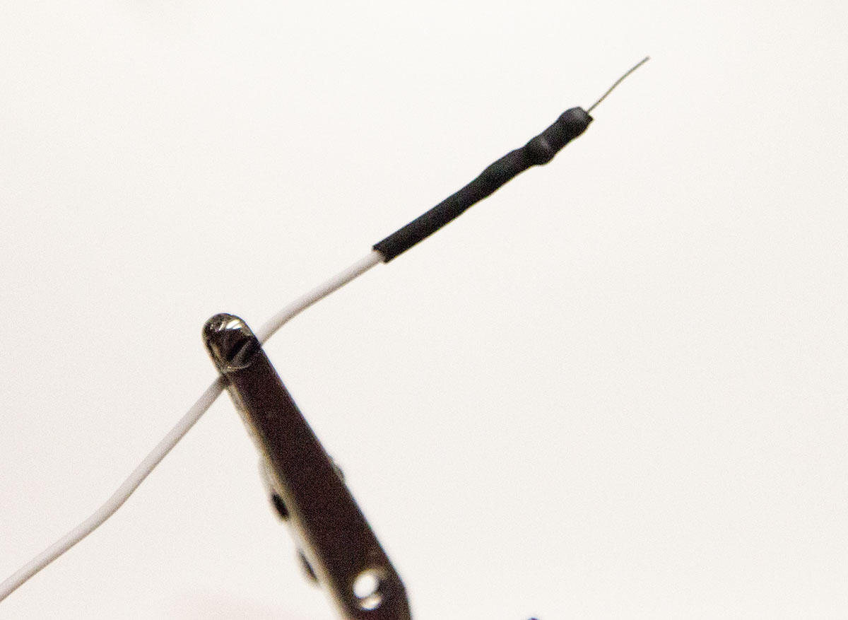
Wire Resistors
Add a 1K resistor to the ends of three wires. Cover with some heat shrink tubing.
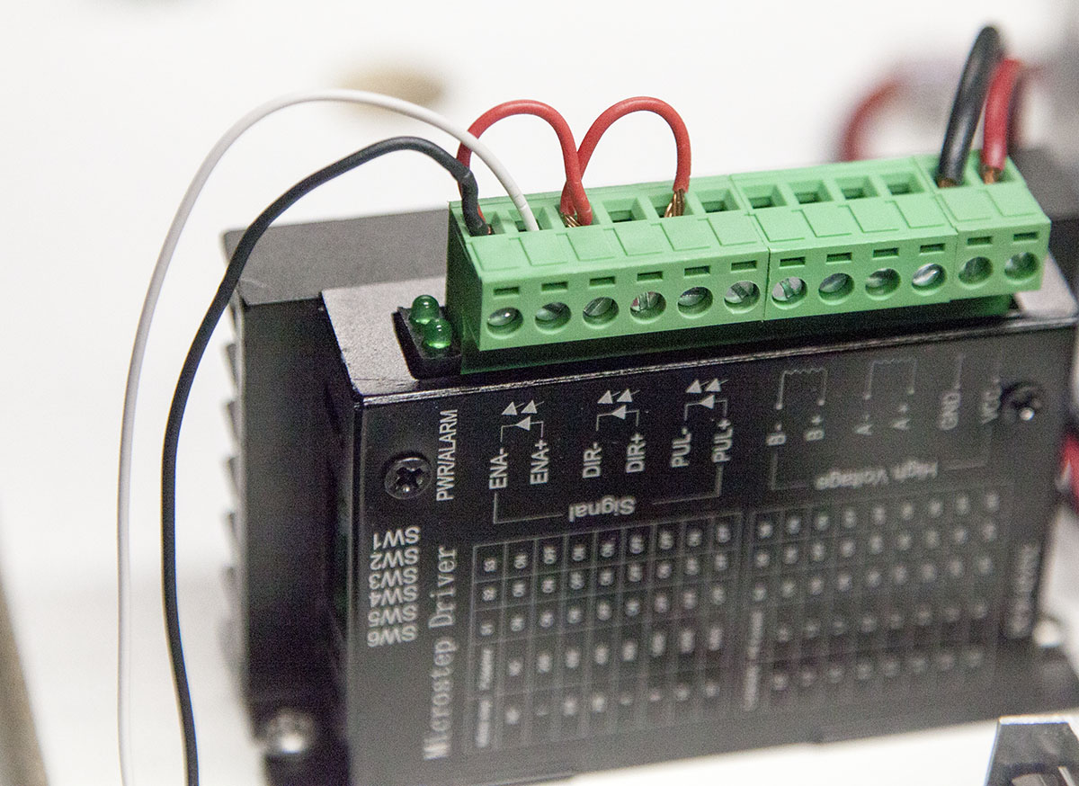
Wire Enable Signal
Add one of the resistor wires to the to the ENA+ on the motor driver and the ENA terminal on the pulse generator.

Wire DIR Signal
Add one of the resistor wires to the to the DIR+ on the motor driver and the DIR terminal on the pulse generator.

Wire Pulse Signal
Add one of the resistor wires to the to the PUL+ on the motor driver and the PUL terminal on the pulse generator.
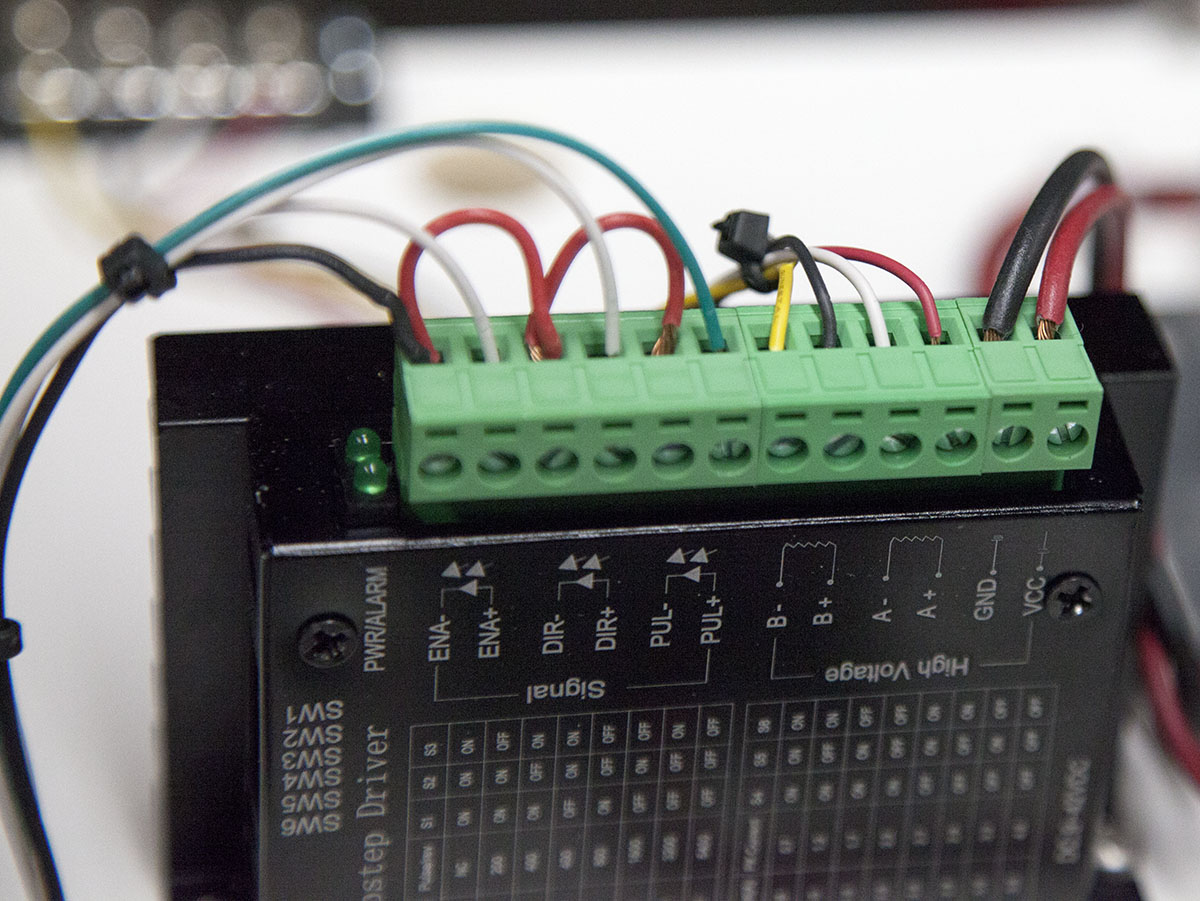
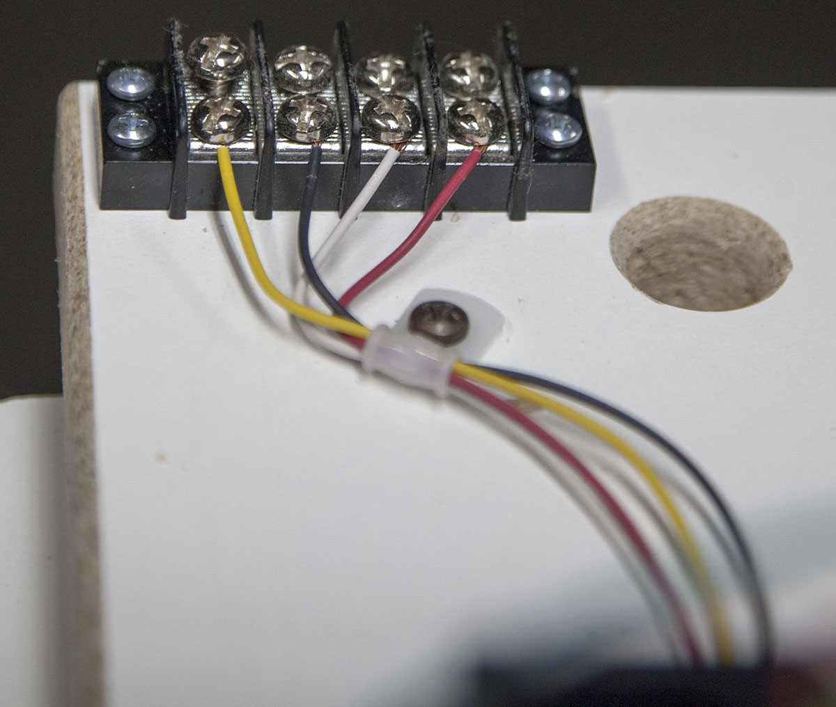
Wire Motor Leads
Connect the four motor leads on the driver to a four position terminal block as shown here.
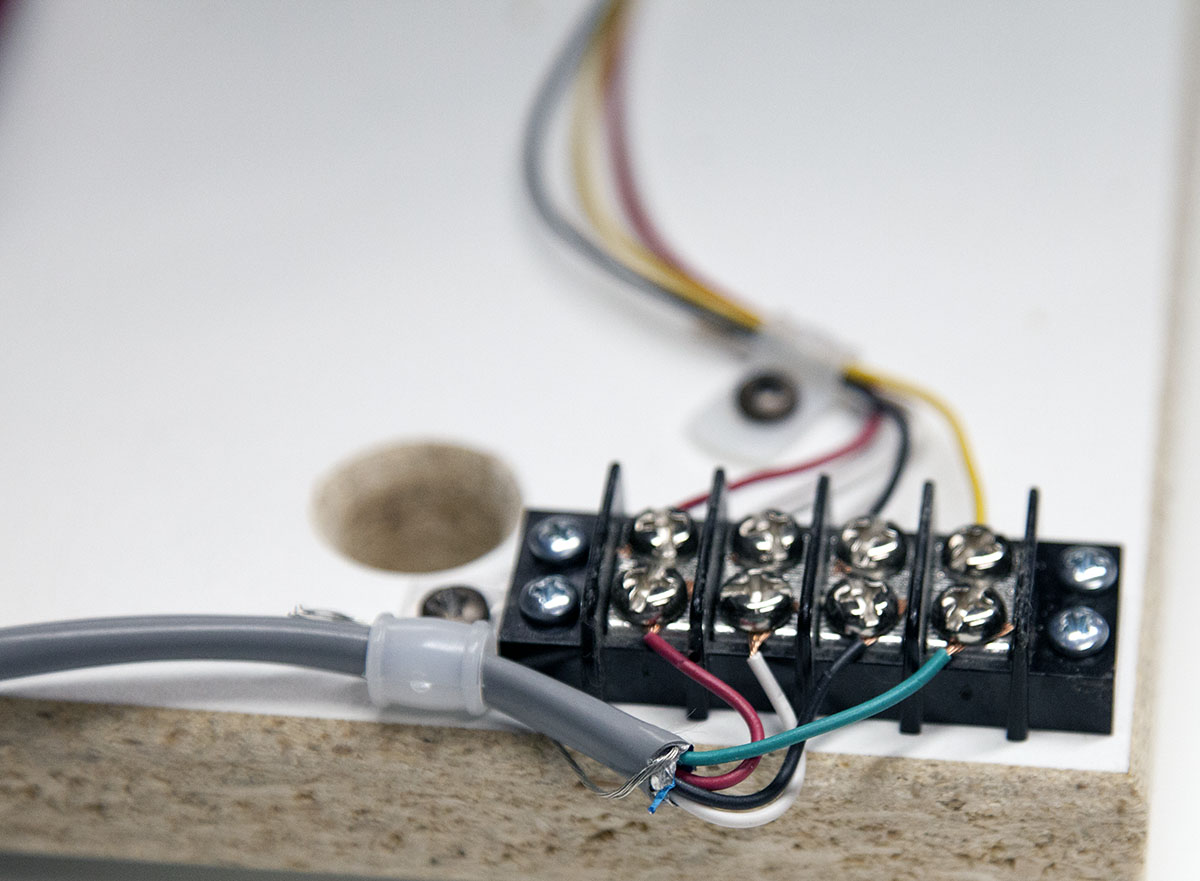
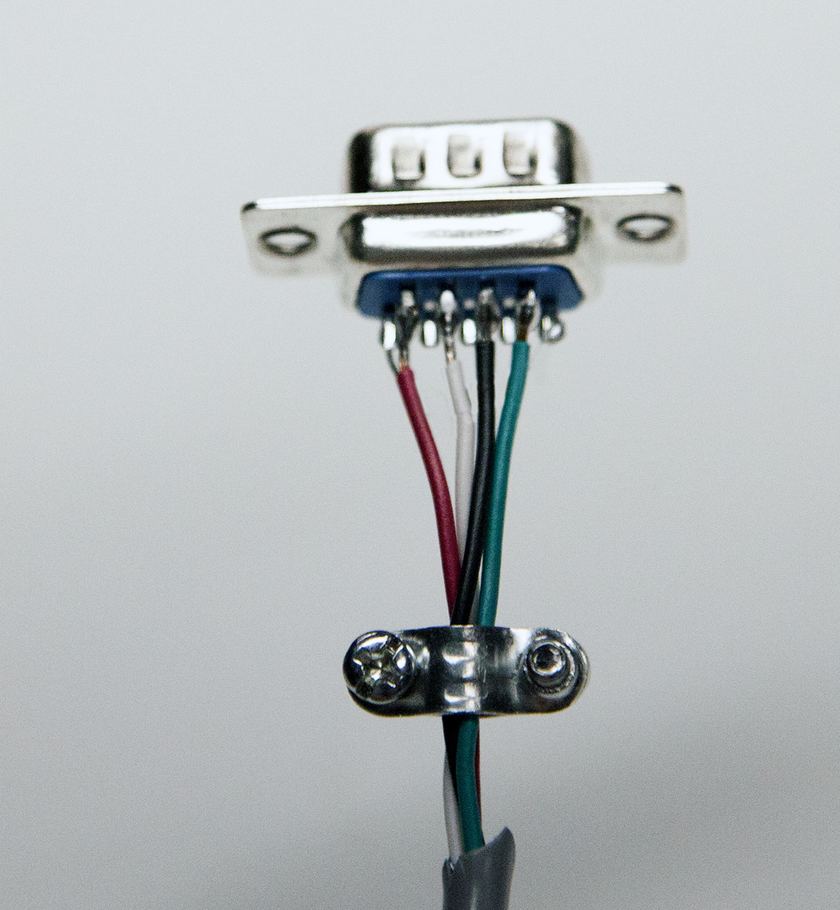
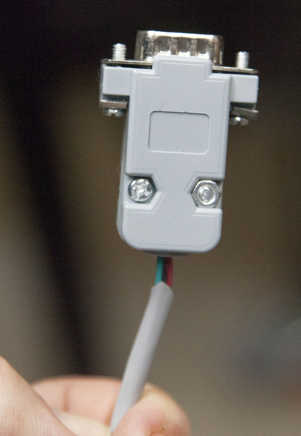
Add a Motor Connector
You can wire your motor connectors to the terminal block, or you can add a connector.
Here I wire a 9-pin connector to the terminal block.
Operation
Power LED
The power LED lights when power is applied tot he pulse generator.
Speed Control
Use the know to adjust the speed of the motor.
- Counter Clockwise = Slow
- Clockwise = Fast
Enable
To turn on the driver and start the motor moving, push the left button down. The red LED next to the button will light when enabled.
Direction
Push the right button to change the direction.
Conclusion
Some things to keep in mind. The pulse generator does not have acceleration of deceleration curves so it is fairly easy to stall the motor at high speeds.
Here is the Stepper Motor Tester in action:
Storage
Here is the stepper motor tester hanging on a pegboard wall.