
This article was originally written back when I was designing the very first CNCCS prototype. As such it is a little out of date. I am in the process of updating this article so please be patient.
CAP 04
While I will be looking at the voltage based THC, I decided to start with a capacitance based THC. The one featured in this article is called the “CAP 04”.
The CAP 04 THC is available from CNC4PC. The one I will be using, I purchased through them: CAP04 THC
Mine looks a little different than the one shown on their site as the 6-pin connector has been replaced by the DB9 connector and small breakout board.
Here are some of the advantages and disadvantages I have found using a capacitance based THC.
Advantages
Works with Flame Cutters
Prevents work from diving on corners
Can work as an IHS even on a painted or rusty surface
Can perform THC activated test runs without plasma torch operating.
Disadvantages
Much more work to integrate into the system as it has physical component
Because of the sensing size, the torch will start to descend at about 1/2” from the edge of the stock.
In the Box
To package contained the following:
CAP 04 Controller
CAP 04 Sensor
47mm Sensor Ring (Plasma)
69mm Sensor Ring (Oxy)
Sensor Cable
Breakout Board
Breakout Board 9pin Cable
There is no documentation included, so you must go online to the CNC4PC and AGELKOM website. Be forewarned, the documentation is kind of spread out and a little hard to follow. As I figure things out, I will document them here and hopefully it will save others some time.
Mounting The Sensor
The first task is to mount the sensor. The BNC cable included is used to connect the sensor to the controller box.
CAP04 Sensor Mount
In order to attach the CAP04 sensor module to the CNC, I built this mount.
The mount consists of three parts and supporting hardware.
The mount assembly is attached to the Z carriage with two 1/4 hex bolts.


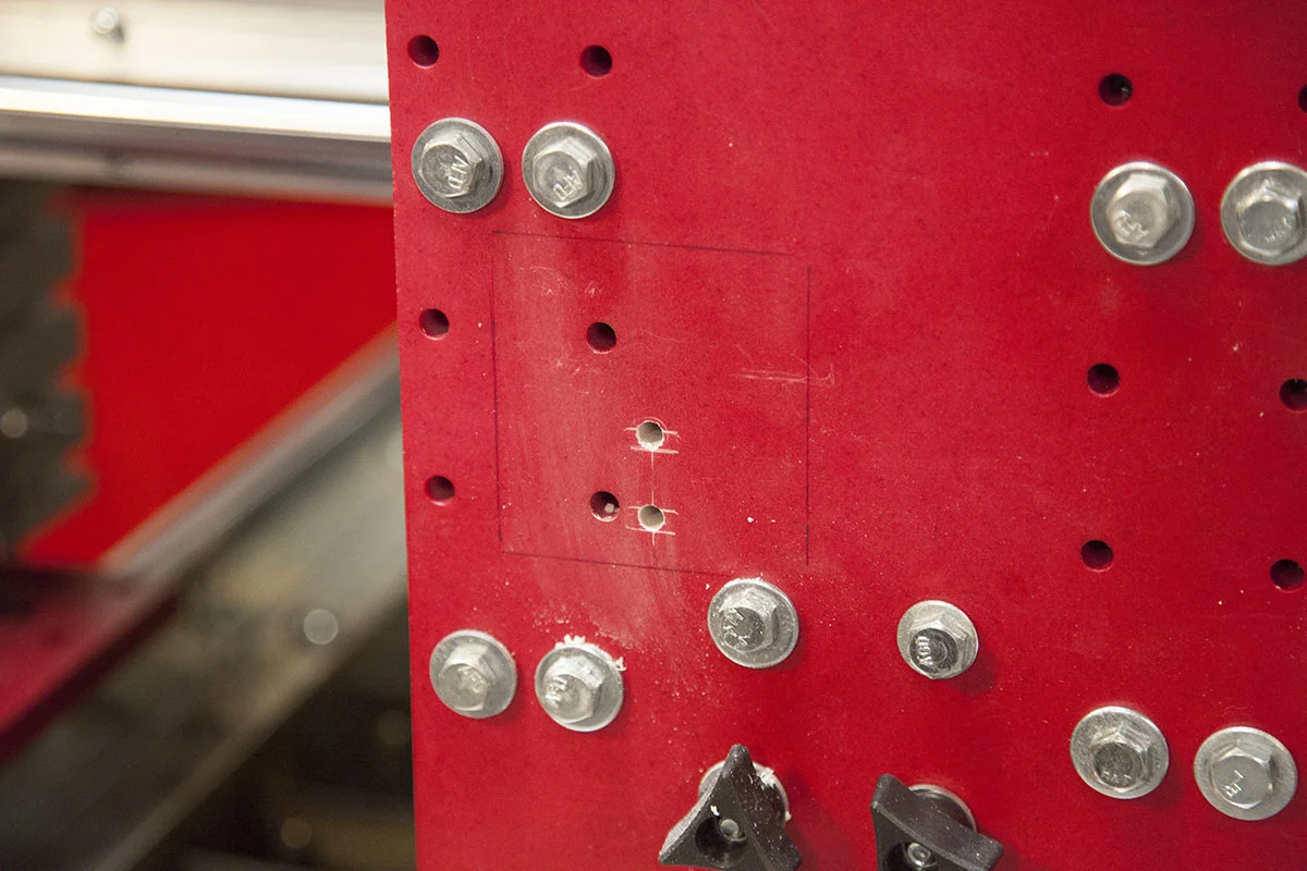


I use the mount to mark the holes on the Z carriage.
I mark and drill holes for a 1/4" Tap.
Once tapped, the assembly is mounted with two 1/4" bolts. There is enough room in the two slots to dial in the sensor ring as needed.
The sensor module is installed and the 4 nuts on the mount tightened.
Mounting the Controller
The CAP 04 needs ti be mounted within range of the included 3ft BNC cable.
This means it will be mounted on the Z carriage.
I removed the cover and used the controller to mark the location of the two mounting holes.
I drilled and tapped the two holes for a 10-24 machine screw. I then attach the controller using two 10-24 x 1" machine screws.
The cover is then installed.
The BNC cable is then used to attach the sensor to the controller.
Grounding the CAP 04 Controller
The instructions call for an industrial sized ground wire, which is not ideal for this build.
I used a 12Ga stranded wire for mine. Its bolted to the case of the Cap 04 controller.
The wire routs its way through my various drag cables and is then attached a bracket attached to my CNC frame.
Here I have tied my various grounds.
Outside Ground Rod
Plasma cutter Work Clamp
Electronics Ground
CAP 04 Ground
Powering the CAP 04
The CAP 04 needs an isolated 24V power source to opperate correctly.
I purchased this MeanWell DIN rail power supply.
Next, next the included breakout board is mounted to my DIN rail board and wired to the 24V power supply.
V- on the power supply is connected to 0V on the board.
V+ on the power supply is connected to +V on the board.
Connecting the breakout board
The Cap 04 is connected to the breakout board via a DB9 cable.
I did move the breakout board, so that the cable was less likely to get jarred as the connector on the board has no reinforcement.
Once the cable is connected you should get one or more lights on the CAP 04. In most cases this is going to be the green Down LED.
The included DB9 cable will not be long enough so you will have to add one ore more DB9 cables to get to where your breakout board is installed.
In this little 12" x 24" cutter, I used three cables. On larger builds, you are going to need a custom cable.
LED Test
The CAP 04 does not need the plasma torch to be running in order to operate. Here is a simple LED test I did. The CAP 04 is not yet connected to my CNC so this is only a LED test.
Connecting to Mach 3
In order to get the Cap 04 to talk to Mach3, I need to get it to talk to the UC300 first.
I already have a G540 attached to the UC300, but the Cap 04 cant drive it.
Luckily the CNC4PC has a breakout board that will allow the Cap 04 to talk to the UC300 and then to Mach3.
Its called the C10S. You can pick one up here:
The board has the ability to pull some of the ports high or low. In the case of the Cap 04 we want to pull them low.
In order to interface the 15V signals from the Cap 04, we need to place a 10K resistor in series with each input.
Each of these 4 black wires (heat shrink) has a 10K ohm resistor. I connected the following:
Cap 04 To C10S
Down - Pin 15
Up - Pin 13
Touch - Pin 12
InPos - Pin 11
I connected the C10S to LPT port 3 on the UC300 so in Mach3 I configured the following pins:
THC UP --> Port 3, Pin 13
THC DN --> Port 3, Pin 15
Probe -----> Port 3, Pin 12
Input1 ----> Port 3, Pin 11
I verified the pins were working by doing the LED test and watching the pins in both Mach3 diagnostics, and the UC300 monitor.
With the Cap 04 now talking to Mach 3, I still need to set a few things up in Mach 3. I also have to make some decisions on how and if I want to probe.
Grounding Carriages
The CNC Construction Set plasma cutter is an experimental build meant for quick design changes. As such I am using Corian for the carriage plates. I pick up a whole counter top at my local ReStores for a fraction of what aluminum would costs me. In addition its much easier to machine.
It has a downside though. It is not conductive.
After installing the CAP 04, I got it to work, but noticed that even bring my hand close to the BNC cable or even the adjustment knob would slightly affect the outputs.
This is to be expected from a sensor that is capacitance based. Here is what I did to solve these issues.
The case on the CAP04 controller is tied to the bracket holding my X axis echain shown here.
This bracket is connected to the Z rail.
The bracket is also tied to the echain mount and gantry.
The gantry is tied to the carriage risers.
The Y carriage risers were also grounded to all four Y carriage trucks (two on both sides)
Conclusion
With the CAP04 installed and grounded, I can now start configuring Mach3.
The carriage on the CNC Construction Set were designed to be removed so you can install a router or other accessories.
By removing the plasma carriage you can see how well your allignment is by viewing the sensor ring from the bottom of the carriage.
If you cant get it to line up, you can loosen the bolts holding the CAP04 mount and move it from sided to side to better help allihgn the ring.